 |
|||
|
|
|||
|
Page Title:
Section V. REPAIR OF TORQUE CONVERTER AND PUMP |
|
||
| ||||||||||
|
|
 The drilled capscrew secures camshaft thrust plate to
plunger and plunger spring in position in cylinder block.
front of cylinder block, and serves to lubricate gear train.
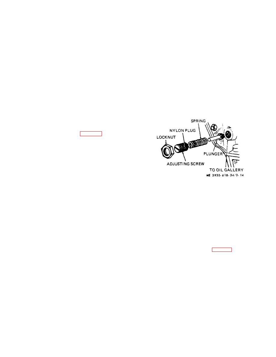
(2) Install pressure regulating valve adjusting
Pressure relief valve should require very little attention
screw and locknut. Make certain valve adjusting screw
under normal conditions. If engine lubricating system
is turned into cylinder block same number of turns
allowed to sludge, valve may not work properly. If
required for removal.
plunger binds in open position, a sharp drop in engine oil
(3) Start engine and operate at about one-half
pressure will occur; or, if plunger binds in closed position,
throttle. Observe engine oil pressure gauge, and adjust
a sharp rise in engine oil pressure will occur. If oil
oil pressure regulating valve to obtain a reading of
pressure should rise or drop sharply, relief valve must be
approximately 15-psi on gauge. After engine reaches
disassembled and checked for damage or sludge.
normal operating temperature. operate engine at high
Whenever oil pump or engine is disassembled. all
idle speed, adjust pressure regulating valve to obtain a
reading of 35-40 psi on oil pressure gauge, and tighten
components of oil pressure relief valve assembly should
locknut. No further adjustment of valve should be
also be removed, thoroughly cleaned, and inspected.
necessary.
NOTE
(4) After engine has been run-in, oil pressure
A gasket between adjusting screw
operating range (with stabilized engine temperature)
locknut and cylinder block is not
is 25- to 35-psi at rated engine speed.
required because of nylon plug
located in side of adjusting screw
which prevents oil leakage past
threads.
b. Removal and Inspection.
(1) Loosen locknut (fig. 3-14) and remove
adjusting screw from cylinder block. While removing
adjusting screw, count number of turns required for
removal.
(2) Remove valve spring and plunger from
cylinder block.
(3) Wash all parts thoroughly in (Spec. P-
D680) and inspect. Replace any worn or damaged parts.
(4) Inspect valve seat in cylinder block and
clean if necessary.
c. Installation and Adjustment.
Figure 3-14. Oil pressure relief valve.
(1) Lubricate plunger with clean oil and install
Section V. REPAIR OF TORQUE CONVERTER AND PUMP
b. Test.
3-15. Torque Converter and Pump
(1) Pump pressure.
a. General. The "Power Shift" is dependent upon
(a)
To check pump pressure. install a
correct operating pressures for efficient operation. If in
pressure gauge calibrated to 300-psi, in the port marked
doubt, the pressures should be checked.
for the
"P" on the right side of the transmission. Leave the
following: Pump pressure, converter pressure, clutch
transmission in neutral and start the engine. Accelerate
pack pressure, and clutch cooling oil pressure.
the engine to full governed speed and note the pressure
NOTE
Oil temperature should be 80 to 100
indicated on the pressure gauge (fig. 3-15).
F, when checking pressure at idle
speed.
3-20
|
|
Privacy Statement - Press Release - Copyright Information. - Contact Us |