 |
|||
|
|
|||
|
Page Title:
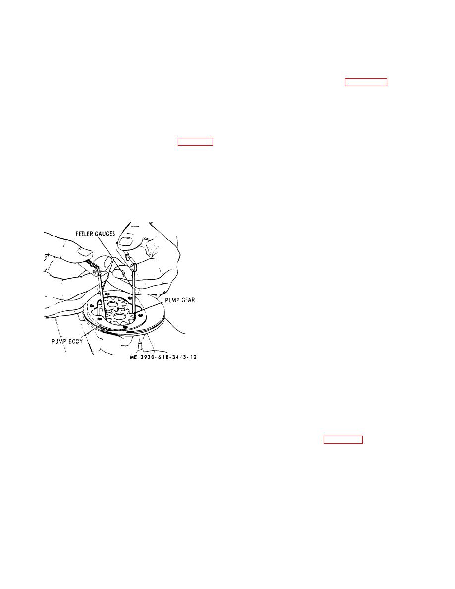
Figure 3-12. Checking oil pump radial clearance. |
|
||
| ||||||||||
|
|
 from pump driving gear and pump body. d. Cleaning
0.004inch. Specified diameter of both pump drive shaft
and Inspection. If dirt and sludge are allowed to
and idler gear shaft is 0.4990-inch - 0.4995-inch. Pump
housing bore is 0.5005-inch - 0.5015 -inch; idler shaft
accumulate in engine lubricating system, oil pump wear
bore is 0.500-inch - 0.501-inch. If parts are worn or
may be rather pronounced in a comparatively short time.
damaged, replace pump.
When oil is kept clean and oil filter has been properly
(3) Thoroughly clean oil pump suction screen.
serviced wear on these parts should be very slight.
e. Assembly. Refer to figure 3-11 for relative
Wash all oil pump components in clean solvent, and
position of parts and assemble pump as follows:
thoroughly inspect and check parts as follows:
(1) When installing gears on idler shaft (14)
(1) Inspect pump gear teeth, inside of pump
or drive shaft (3), press shaft gear into gear until end is
body, and inner face of cover for wear and scoring. Gear
approximately flush with end of gear.
teeth, inside of pump body, and inner face of cover must
CAUTION
be smooth with no scratches, score marks, or rough
spots. Also, inspect pump shafts and shaft bores in
Shaft must not protrude past oil
pump body for excessive radial clearance (fig. 3-12)
pump cover end of gear.
between pump gears and pump body (0.001-inch to
(2) Lubricate pump drive shaft and insert (with
0.002-inch). End clearance (between pump gears and
drive gear in position) into bore in pump body.
pump cover) of gears in pump body is 0.002-inch - 0.
(3) Place pump body in position in a press,
004-inch, and must not exceed 0.006-inch. To check
supporting assembly on drive gear end of shaft. Place
clearance, lay pump cover across pump body. Insert a
pump driving gear in position! or: upper end of shaft,
feeler gage between pump cover plate and pump gears.
aligning pinhole in gear ,with hole in shaft. Press gear
Backlash between pump gears can be checked with a
onto shaft until pinhole in gear and shaft are aligned.
feeler gage and should not exceed 0.020-inch.
Install new roll pin.
(4) Lubricate idler gear shaft (4) and install
pump gears (15) and shaft in position in pump body.
Check dimension between gears and bottom face of
pump body. End clearance of gears should be 0.002-
inch - 0.004-inch.
(5) Place pump cover (9) in position on pump
body (4) and secure with the capscrews (11) and
lockwashers (10).
NOTE
No gasket is required between cover
and pump body.
(6) Place pump suction screen (12) in position
on bottom of pump body and secure with screen
retaining wire (13).
(7) After pump is completely assembled, it
must turn freely when rotating drive gear (1) by hand.
f. Installation.
The
following
installation
instructions apply when engine has not been
disassembled for complete overhaul or when oil pump
Figure 3-12. Checking oil pump radial clearance.
has been removed with engine in truck. For pump
installation instructions at engine overhaul. refer to g
(2) Inspect pump shafts for wear with a
below.
micrometer and pump body wear with a feeler gage.
(1) Make certain distributor rotor is aligned
Inspect for excessive wear or scoring and replace if
with reference mark made on side of distributor housing
necessary. Specified clearance between pump drive
as instructed in b (1) above.
shaft and pump housing bore is 0.0010-inch - 0.0025-
(2) Before installing oil pump in cylinder block,
inch and must not exceed 0.004 - 0.006-inch. Specified
use dial as illustrated in figure 3-13 to position offset of
clearance between idler gear shaft and pump housing
pump drive gear to the right and toward the rear of
bore is 0.0005 inch - 0.0029-inch, and must not exceed
cylinder block so that slot will be at an angle of 5: 30-to
11: 30-o'clock.
3-18
|
|
Privacy Statement - Press Release - Copyright Information. - Contact Us |
