 |
|||
|
|
|||
|
Page Title:
Disassembly of Directional Control Switch |
|
||
| ||||||||||
|
|
 TM 10-3930-609-35
3-108.
Disassembly of Directional Control Switch
e. Unhook springs from pins in arms and remove
springs.
a. Remove screw and lockwasher and disengage
f. Remove screws securing clips to housing and
lever from shaft.
remove clips and arm from housing.
b. Remove screws which secure cover to housing
g. Remove screw, lockwasher and flatwasher
and remove cover and washers.
securing carrier to end of shaft; then, remove carrier,
bushing and shaft from housing.
c. Squeeze contact fingers together; then, rotate
1/4 turn and withdraw contact fingers and spring from
h. Remove nut, lockwasher and flatwasher; then,
.carrier.
remove trip shaft trip lever housing.
d. Remove screws securing terminal boards in
housing and lift out terminal boards.
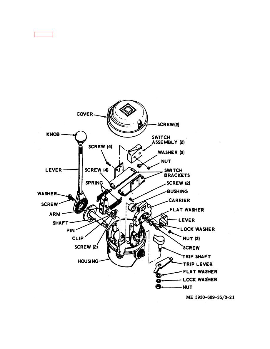
Figure 3-21. Directional control switch, exploded view.
3-38
|
|
Privacy Statement - Press Release - Copyright Information. - Contact Us |