 |
|||
|
|
|||
|
|
|||
| ||||||||||
|
|
 ELECTRICAL
c. Operate the alternator for 15 minutes at
approximately 1500 engine RPM (approximately
3500 alternator RPM). Leave cover on regulator
to establish operating temperature. Accessories
and lights must be turned off.
d. After the 15 minute warm-up period, cycle the
alternator by the following procedure:
(1) Turn the variable resistor in the field circuit
to the full resistance position.
(2) Disconnect then reconnect the jumper lead
at the "BAT" terminal of the "Alternator."
(3) Return the variable resistor to the closed or
"no resitance" position.
(4) Bring engine speed up to 2450 RPM
(approximately 6000 alternator RPM) and note
the voltage setting. Refer to the Specification
Listing for specifications. The regulator should
be operating on the upper or shorting contacts.
If it will not operate on the upper contacts, the
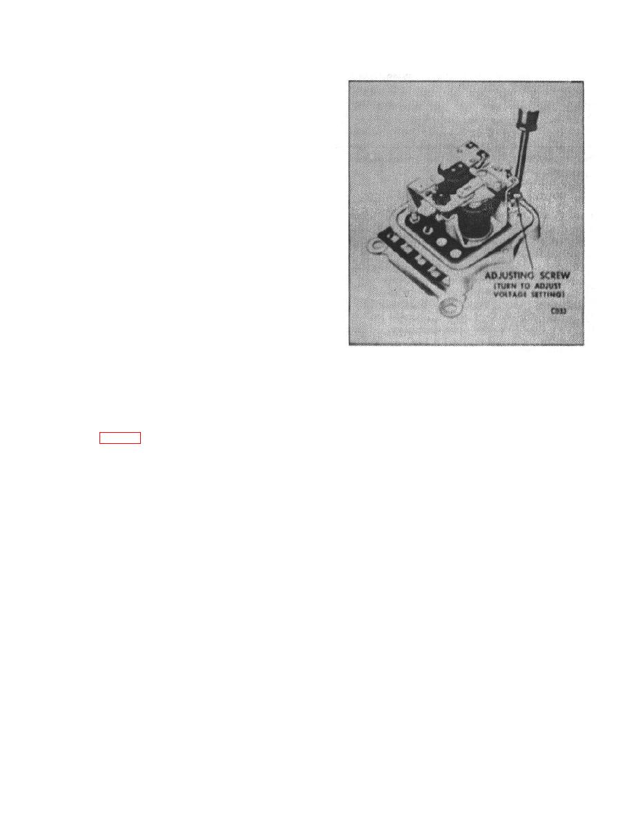
Figure 24.
battery is in an extreme state of discharge, and
must be at least partially charged before
f. After making the setting, cycle the alternator as
proceeding.
covered in Step "d" above.
e. To adjust the voltage setting while operating on
g.
Then, operate at 2450 engine RPM
the upper or shorting contacts, turn the adjusting
(approximately 6000 alternator RPM), and note
screw. (Fig. 24)
setting. Adjust if necessary.
CAUTION: Always make final setting by turning the
h. Always cycle the alternator as covered in Step
screw clockwise. This insures that the spring-
"d", before reading the final voltage setting on the
holder will be against the head of the screw. If it is
necessary to turn the screw counterclockwise, turn
it until the screw head is approximately 1/8"', above
i. After making the voltage setting while operating
the adjusting bracket, then pry holder up against
on the upper set of contacts, check the voltage
screw head, then turn clockwise to make setting.
setting while operating on the lower set of contacts
as follows: Slowly increase the resistance of the
variable resistor with the engine operating at 2450
RPM (approximately 6000 alternator RPM) until
the regulator begins to operate on the lower set of
contacts. Then note the voltage reading, and
refer to Specification Listing for specifications,
B-69
|
|
Privacy Statement - Press Release - Copyright Information. - Contact Us |
