 |
|||
|
|
|||
|
|
|||
| ||||||||||
|
|
 TM 10-3930-242-34
forced exerted by the governor high speed
weights will equal the force exerted by governor
h i g h speed spring. Adjustment of the maximum
n o - l o a d speed is accomplished by changing the
t e n s i o n on the high speed spring.
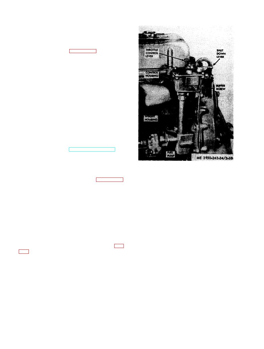
t h e governor.
( 1 ) Disconnect linkage to governor control
( 2 ) Remove screws and lockwashers attach-
i n g governor cover to governor housing.
( 3 ) Remove two bolts and lockwashers at-
taching spring housing to governor housing.
R e m o v e spring housing and gasket.
(4) Loosen high speed spring retaining
l o c k n u t and remove the high speed spring re-
tainer and spring.
(5) Loosen hose clamp.
(6) Remove rocker cover (TM 10-3930-
242-12).
(7) Disconnect fuel rod from injector control
tube lever. Remove clip holding fuel rod to diffe-
r e n t i a l lever.
( 8 ) Disconnect fuel lines from fuel pump
and remove fuel pump (TM 10-3930-242-12).
(9) Remove five bolts from governor weight
housing and two bolts from governor control
housing.
( 1 0 ) Remove governor and gasket from en-
gine.
(5) Remove screws (6) and washers (7) hold-
and disassemble the governor assembly cover,
ing fork (10) to operating shaft (14).
as follows:
(6) Lift the shaft (8) and weight carrier as-
(1) Remove four screws on top of the control
sembly (9) from the governor weight housing
h o u s i n g and remove housing cover.
(40).
( 2 ) Loosen governor throttle control lever
(7) Remove screw (11) washers (12 and 13)
r e t a i n i n g bolt and lift control lever from throt-
holding bearing (20) in control housing (31).
tle shaft.
(8) Lift the shaft assembly (14) from the
(3) Remove retaining ring and washer.
housing (31).
W i t h d r a w throttle shaft from cover.
(9) Place a rod approximately 18 inches long
(4) Loosen governor shut down retaining
through control housing and knock out plug (15)
b o l t and remove hardware, as described above.
f r o m weight housing.
e. Disassembly of Governor Weight H o u s i n g .
(10) Remove snapring (16) and press bearing
( 1 ) Remove the gear retaining nut (1, fig.
(17) from weight housing.
(11) Remove spring clip (18) and washer from
and spacer (4) from shaft.
g o v e r n o r operating shaft lever (20) and remove
( 2 ) Remove screw (5) holding bearing sup-
g o v e r n o r differential lever (19).
port (32) in place.
( 1 2 ) If necessary, press bearing (21) and
o p e r a t i n g shaft lever (20) from shaft.
(3) Turn bearing support (32) until the large
(13) If necessary, press pins (22 and 23) from
opening is centered over the fork (10) on operat-
levers (19 and 20).
ing shaft (8).
f. Disassembly of Weight Shaft Assembly.
( 4 ) Lift up on weight shaft until there is
(1) Press bearing retainer support (32) from
e n o u g h clearance to insert socket wrench to re-
weight shaft (8).
move screws and washers holding fork on to
( 2 ) If necessary, remove snapring (33) and
shaft.
|
|
Privacy Statement - Press Release - Copyright Information. - Contact Us |