 |
|||
|
|
|||
|
|
|||
| ||||||||||
|
|
 TM10-3930-242-12
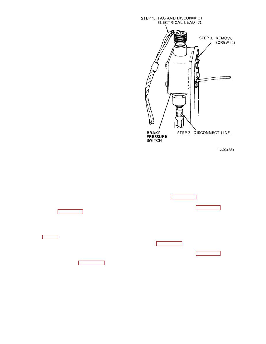
a. General. The pressure switch is located on the
rearward structure member of the battery carrier,
adjacent to the hydraulic oil tank. For access,
remove the left engine side panel. From this access
point, the device is located high and to the left. An
alternate access is through the battery carrier,
adjacent to the hydraulic oil tank. The switch is
activated when the accumulator hydraulic pressure
drops below 300 psi and a buzzer warning indicates
that it is unsafe to operate the forklift truck.
b. Testing.
(1) Disconnect one of the two wire leads that go
to the brake pressure switch.
(2) Start and operate the engine for at least
one minute to build up the hydraulic oil pressure in
the accumulator.
(3) Using a multimeter, and with one wire lead
disconnected, test for continuity across the two wire
lead terminals. There should be no continuity in-
dicated.
(4) Stop the engine and operate the brake pedal
several times until you are sure that all hydraulic
pressure in the accumulator is exhausted.
{5) Again, test across the terminals. This time
there should be continuity indicated.
(6) Replace a defective brake pressure switch.
c.. Removal
WARNING
Always bleed off the pressure before
a Magnetic Switch.
opening any part of the hydraulic brake
(1) Inspection. Inspect switch for corrosion and
system by operating the brake pedal
loose connections. Check wiring for breaks and
several times while the engine is not
deterioration. Replace defective parts.
running. Failure to observe this warning
(2) Removal. Tag and remove the four electrical
may result in severe injury to personnel.
wires. Refer to figure 4-28 and remove mounting
(1) Bleed off hydraulic pressure by operating
screws and nuts.
the brake pedal until all pressure has been depleted.
(3) Installation. Refer to figure 4-28 and install
(2) Refer to figure 4-27 and remove the brake
the magnetic switch.
p r e s s u r e switch.
b. Starter Pressure Switch.
d. Cleaning and Inspection.
(1) Inspection. Inspect switch for corrosion and
(1) Clean the brake pressure switch with a cloth
loose connections. Check wiring for breaks and
that has been dampened in drycleaning solvent
deterioration. Replace defective parts.
(item 1, App F). Do not immerse the switch in
(2) Removal. Tag and remove electrical wire.
solvent or allow it to be saturated by solvent.
Refer to figure 4-28 and unscrew switch from its
(2) Inspect the switch for corrosion, cracks,
mounting hole.
damaged, and other damage. Replace a
(3) Installation. Refer to figure 4-28 and install
defective switch.
the starter pressure switch.
e. Installation. Refer to figure 4-27 and install
the brake pressure switch.
|
|
Privacy Statement - Press Release - Copyright Information. - Contact Us |
