 |
|||
|
|
|||
|
Page Title:
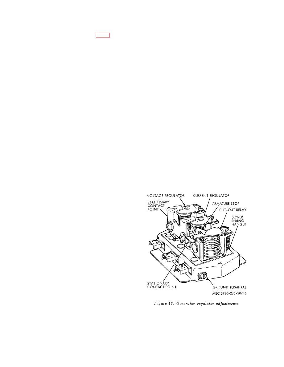
Figure 16. Generator regulator adjustments |
|
||
| ||||||||||
|
|
 m e a s u r e gap, between armature
proximately 15 minutes without
and. center of core, with feeler gage.
electrical load to reach operating
The correct gap is 0.025 to 0.027
temperature.
inch. If adjustment (fig. 16) is re-
d. Cycle the generator by moving
quired, loosen the two screws in
the voltmeter lead from the reg-
back of relay, then raise or lower
ulator B terminal to the G ter-
the armature until correct airgap
minal. Retard generator speed
is obtained.
Tighten mounting
until the generator voltage is re-
screws, then recheck airgap.
duced to 4 volts. Then move the
voltmeter lead back to the B ter-
(b) Point opening. Check point opening
minal. Bring the generator back
and adjust to a correct reading of
up to specified speed and note the
0.015 inch. Adjust by bending up-
voltage setting. The correct volt-
per armature stop.
age setting range is 14.3 to 14.5
(c) Closing voltage. The closing voltage
volts .
should be 12.6 to 13.6 volts. Con-
e. Turn the adjusting screw clock-
nect a voltmeter between the regu-
wise to increase and counterclock-
lator terminal and ground. Slowly
wise to decrease the voltage set-
increase generator speed and ob-
ting.
serve the relay closing voltage. De-
2. Variable resistance method. Proceed
crease generator speed and make
as follows:
sure the points open. Points should
a. Connect a variable resistance, of
open at 3.0 to 5.0 amperes.
not less than 25 watts, and an
(2) Voltage regulator. The voltage regu-
ammeter into the charging circuit
lator requires two checks and adjust-
and in series with the battery at
ments as follows:
the regulator B terminal.
(a) Airgap. With the battery discon-
b. Connect a voltmeter from the
nected, push the armature down and
regulator B terminal to ground on
check the airgap. Airgap should be
the regulator base.
0.048 to 0.052 inch. If adjustment
is needed, loosen the contact mount-
ing screws and raise or lower the
contact mounting bracket as re-
quired. Make sure the contact points
a r e aligned and the mounting
screws securely tightened after ad-
justment.
(b) Voltage setting. The voltage regu-
lator setting can be checked and
adjusted by using either a fixed or
variable resistance method.
1. Fixed -ohm resistance method.
Proceed as follows:
a. Connect a -ohm fixed resistor
of not less than 25 watts into the
charging circuit at the B terminal
and in series with the battery.
b. Connect a voltmeter from the reg-
ulator B terminal to ground on
regulator base.
c. Operate the generator, with the
regulator cover in place, for ap-
32
AGO 6217A
|
|
Privacy Statement - Press Release - Copyright Information. - Contact Us |