 |
|||
|
|
|||
|
Page Title:
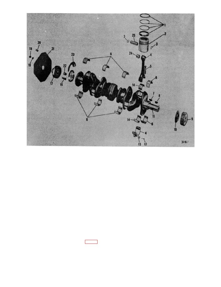
Figure 10. Crankshaft, connecting rod, and piston, exploded view. |
|
||
| ||||||||||
|
|
 1 Ring set, piston
14 Bearing, sleeve, connecting rod
2 Piston
15 Seal, rear bearing filler block
3 Rings, retaining, piston pin
16 Bolt, converter hub and plate
4 Rod assembly, connecting
17 Hub, converter-to-crankshaft
5 Bolt, machine, connecting rod cap
18 Lockwasher
6 Bearing set, crankshaft
19 Nut
7 Key, woodruff
20 Spacer, converter mounting
8 Key, woodruff
21 Plate, adapter, converter housing-to-cylinder block
9 Gear, timing
22 Bearing, sleeve, crankshaft pilot
10 Plate, thrust
23 Guard, rear bearing oil seal
11 Crankshaft
24 Bearing, sleeve, piston pin
12 Pin, cotter
25 Pin, piston
13 Nut, slotted, hexagon
Figure 10. Crankshaft, connecting rod, and piston, exploded view.
29. Connecting Rods and Bearings
a. Removal.
assembly (4) with sleeve bearing
(14).
(1) Block truck up at suitable working
(5) Push out connecting rod assembly (4)
height.
and piston (2) with ring set (1) and the
(2) Remove cylinder head (TM 103930-
upper sleeve bearing half (14) through
222-20).
top of cylinder.
(3) Remove oil pan (par. 14a).
(6) Repeat steps (4) and (5) for remaining
(4) Remove the cotter pins (12, fig. 10) and
five pistons.
nuts (13) from bolts (5), and take off
(7) Remove sleeve bearings from
lower half of connecting rod 18
connecting rod assembly halves.
AGO 7010A
18
|
|
Privacy Statement - Press Release - Copyright Information. - Contact Us |