 |
|||
|
|
|||
|
Page Title:
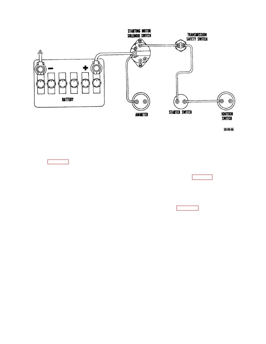
Figure 39. Electrical starting circuit. |
|
||
| ||||||||||
|
|
 TM 10-3930-222-20
Figure 39. Electrical starting circuit.
down until the correct airgap reading of
42. Engine Voltage Regulator
0.020 inch is obtained.
Tighten the
armature mounting screws and recheck
Refer to figure 43 and remove the regulator as
airgap.
follows:
(b) Point opening. Check the point opening and
a. Removal.
adjust as shown in figure 45 to a correct reading
(1) Disconnect and tag the generator and field wires
of 0.020 inch by bending the upper armature
and the battery lead at the regulator.
stop.
(2) Remove the capscrews and lockwashers that
(c) Closing voltage. The closing voltage should be
secure the regulator to the bracket and remove
11.8 to 13.5 volts. Hook up the test equipment
the regulator.
(fig. 46) and adjust the closing voltage as
shown in figure 47 by turning the adjusting
b. Installation. Reverse procedures in a above.
screw. Turn the screw clockwise to increase
spring tension and closing voltage; turn the
c. Testing and Adjusting.
screw counterclockwise to descrease spring
(1) Cutout relay. The cutout relay requires three
tension and closing voltage.
checks and adjustments, as follows:
(2) Voltage regulator. The voltage regulator requires
(a) Airgap. With the battery disconnected,
two checks and adjustments as follows:
press the armature down as shown in
(a) Airgap. With the battery disconnected, check
figure 44 until the points just close and
the airgap for a read ing of 0.075 inch. If
measure the airgap between the armature
adjustment is needed, use a 3/8-inch box-en(
and the center of the core. If adjustment
is required, loosen the two armature
screws and move the armature up or
80
|
|
Privacy Statement - Press Release - Copyright Information. - Contact Us |