 |
|||
|
|
|||
|
Page Title:
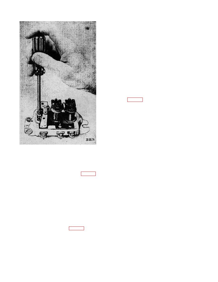
Figure 47. Adjusting cutout relay closing voltage, |
|
||
| ||||||||||
|
|
 TM 10-3930-222-20
(3) Loosen the terminal nut (fig. 58).
(4) Remove the lock screw.
(5) Remove the contact set from pivot pin.
(6) Install the new contact set.
(7) Install the lock screw.
(8) Tighten the terminal nut.
(9) Adjust the contact points (i, below).
(10) Install the rotor and cover.
(11) Install the cap assembly.
i. Contact Point Adjustment. With the distributor
cap removed, and the rubbing block of movable contact
at the high point of the cam, check the contact point gap
by inserting a 0.022-inch wire feeler gage between the
contact points. If an adjustment is necessary, loosen
the lock screw and turn the eccentric screw (fig. 58) to
move the stationary point contact support until the
proper gap is attained. After adjustment is completed,
tighten the lock screw. To check the cam dwell angle
refer to figure 61.
45. Spark Plugs
a. Removal.
(1) Remove the lead assemblies from the
spark plugs.
(2) Unscrew and remove the spark plugs and
gaskets.
b. Cleaning.
(1) Before removal from the engine, the
spark plugs may be cleaned by wiping
with a dry rag.
Figure 47. Adjusting cutout relay closing voltage,
(2) After removal (a above), the spark plugs
may be cleaned by sandblasting.
(5) Install the lead assemblies on the spark
c. Adjusting Gap. Adjust the spark plug gap to
plugs and coil.
0.030 inch, using a round (wire) spark plug gage. To
g. Capacitor Replacement.
obtain proper adjustment, bend the ground electrode
(1) Remove the cap assembly (4, fig. 56).
only.
(2) Remove the rotor (5) and cover (6).
d. Inspection.
(3) Remove the terminal nut and the
(1) Inspect the shell for breaks and stripped
capacitor lead from the terminal.
threads.
(4) Remove the screw and lockwasher that
(2) After removal (a above), check the spark
secure the capacitor to the distributor and
plug insulation for breaks, cracks, or
remove the capacitor.
chips.
(5) Install a new capacitor.
(3) Check for abnormal carbon deposits and
(6) Reverse procedures (1) through (4)
burned electrodes.
above.
e. Tests. Spark plugs may be tested on a spark
h. Contact Set Replacement.
plug tester, using a good spark plug as standard.
(1) Remove the capacitor (g (1)-(4) above).
(2) Remove the rotor (5, fig. 56) and cover
(6).
88
|
|
Privacy Statement - Press Release - Copyright Information. - Contact Us |
