 |
|||
|
|
|||
|
|
|||
| ||||||||||
|
|
 TM 10-3930-634-34
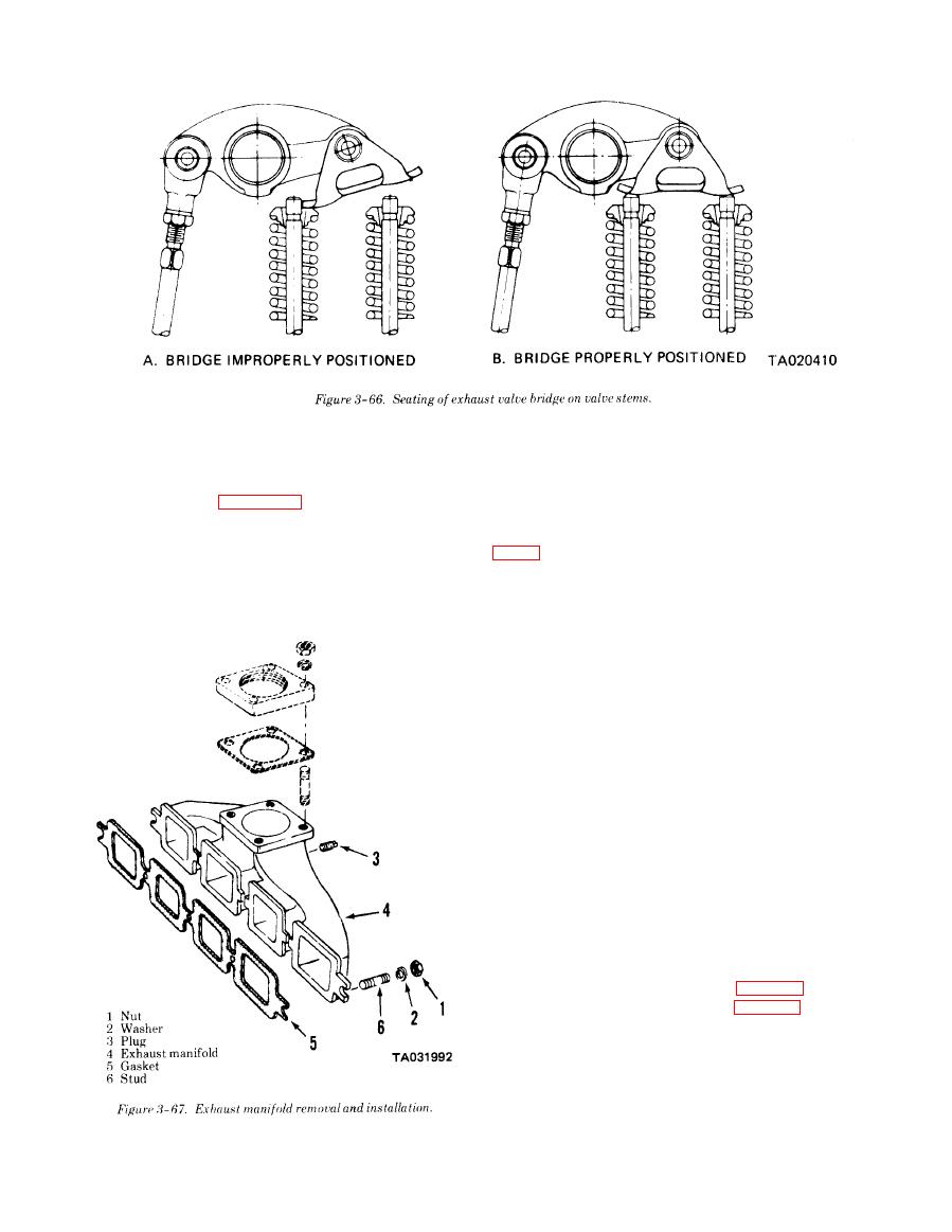
(1) Inspect manifold for cracks or other defects.
b. Removal.
Replace the part if threads are damaged.
(1) Remove exhaust piping and muffler (TM
(2) Inspect studs and nuts for damaged threads.
10-3930-634-12).
Replace the part if threads are damaged.
(2) Remove the exhaust manifold in numerical se-
e. Installation.
quence as shown in figure 3-67.
(1) Install the exhaust manifold with a new gasket
c. Cleaning.
in reverse of numerical sequence as shown in figure
(1) Clean all rust, carbon and oxidized material
from the manifold with a wire brush.
( 2 ) Install muffler and exhaust piping (TM
(2) Clean gasket material from exhaust manifold
10-3930-634-12).
and cylinder head.
d. Inspection.
3-25. Cylinder Head
a. General.
The cylinder head is a one piece casting mounted to the
cylinder block. It may be removed from the engine as
an assembly containing cam followers, cam follower
guides, rocker arms, exhaust valves, and fuel injectors.
To insure efficient cooling, the exhaust passages, valve
inserts and fuel injectors are completely surrounded
with coolant. Water nozzles are inst ailed between each
pair of cylinders in the water inlet ports where coolant
is directed at high velocity against the sections of the
cylinder head subjected to the greatest heat. Gaskets
and seal rings are incorporated to seal the head to the
cylinder block.
b. Removal.
(1) Drain cooling system and engine block (TM
10-3930-634-12).
(2) Remove thermostat, thermostat housing (TM
10-3930-634-12).
(3) Remove exhaust manifold (para 3-24).
(4) Remove rocker arm cover (para 3-16).
CAUTION
When resting cylinder head assembly on
work bench, protect cam follower rollers and
injector spray tips by resting valve side of
head on wooden blocks at least 2 inches thick.
|
|
Privacy Statement - Press Release - Copyright Information. - Contact Us |
