 |
|||
|
|
|||
|
Page Title:
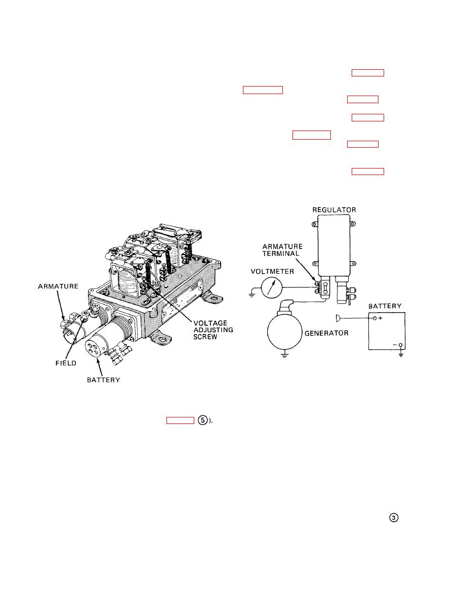
Figure 3-8. Voltage regulator adjustment (sheet 3 of 5). |
|
||
| ||||||||||
|
|
 TM10-3930-634-34
b. Exhaust Valve Adjustment.
check various settings for possible changes in previous
(1) Cold Engine.
adjustment. However, if the cylinder head, governor,
or fuel injectors have been removed and/or replaced,
-
then specific preliminary adjustments are required be-
in figure 3-12.
fore the engine is started. The preliminary adjust-
(c) Install rocker arm cover (para 3- 16).
ments consist of the first four items in the following
(2) Hot Engine.
sequence. The remaining items complete the list of en-
gine adjustments to be performed.
(1) Exhaust valve clearance adjustment.
observing note in figure 3-12.
(2) Fuel injector timing.
(c) Install rocker arm cover (para 3-16).
(3) Governor gap adjustment.
c. Fuel Injector Timing.
(4) Fuel injector rack control lever adjustment.
(1) Preparation for Injector Timing.
(5) Maximum no-load speed adjustment.
(6) Idle speed adjustment.
(b) Place the governor speed control lever in idle
(7) Governor buffer screw adjustment.
1. CONNECT THE REGULATOR AS SHOWN ABOVE.
2. POLARIZE THE GENERATOR (FIG. 3-8
3. START THE UNIT AND OPERATE AT GOVERNED SPEED FOR 15 MINUTES. THE VOLTMETER
SHOULD INDICATE 28.2 V.
REMOVE THE REGULATOR COVER AND TURN THE ADJUSTING SCREW CLOCKWISE TO INCREASE
4.
THE VOLTAGE SETTING AND COUNTERCLOCKWISE TO DECREASE THE SETTING.
AFTER EACH ADJUSTMENT, CYCLE THE GENERATOR BY REDUCING THE ENGINE SPEED AND
5.
MOMENTARILY OPENING THE VOLTAGE REGULATOR POINTS BY HAND. THIS ELIMINATES
RESIDUAL MAGNETISM IN THE CORE OF THE REGULATOR AND ASSURES A TRUE ADJUSTMENT.
REPLACE THE REGULATOR COVER AND BRING UNIT SLOWLY UP TO OPERATING SPEED.
NOTE THE VOLTMETER INDICATION.
REPEAT STEPS 4 AND 5 UNTIL THE DESIRED VOLTAGE IS OBTAINED.
6.
STOP THE UNIT.
7.
TA032034
Figure 3-8. Voltage regulator adjustment (sheet 3 of 5).
3-10
|
|
Privacy Statement - Press Release - Copyright Information. - Contact Us |
