 |
|||
|
|
|||
|
Page Title:
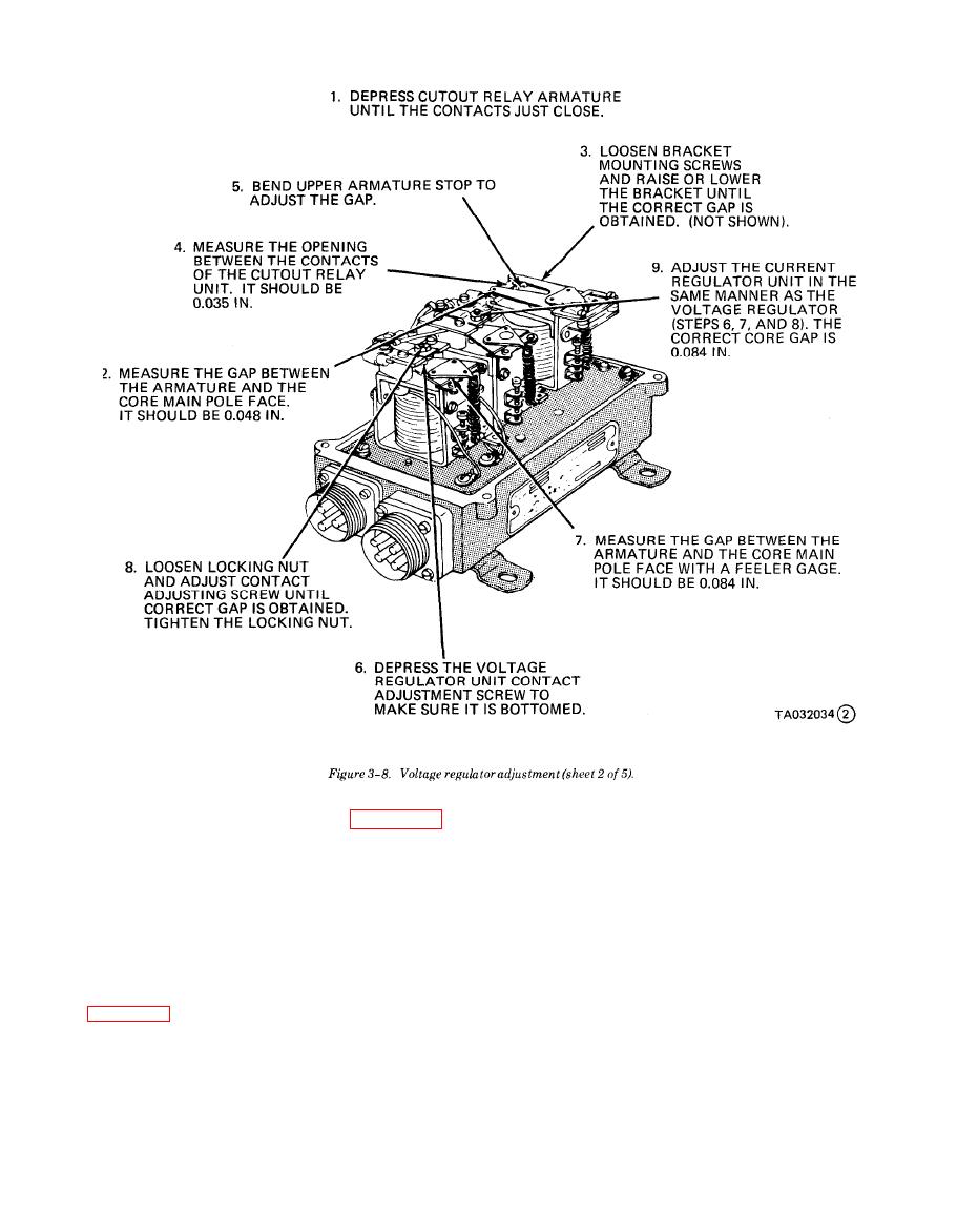
Figure 3-8. Voltage regulator adjustment (sheet 2 of 5). |
|
||
| ||||||||||
|
|
 TM 10-3930-634-34
3-10. G e n e r a l
side. Leaving the pump under pressure the fuel is
forced through the fuel filter and into the upper fuel
a. This section contains information on the mainte-
manifold, then through fuel pipes into the inlet side of
nance of the engine fuel system which is comprised of
the injectors.
the air inlet housing, blower assembly, blower drive
b. Surplus fuel returns from the outlet side of the
and coupling, rocker arm cover, fuel injectors and con-
injectors through outlet fuel pipes into the return
trol lever, fuel pump, governor, and the fuel tank.
manifold and back to the fuel tank. The surplus fuel
b. The fuel system consists of the fuel strainer, fuel
serves as a coolant. In addition to serving as a coolant,
pump, fuel filter, fuel lines and injectors as shown in
circulation of the fuel bleeds any air or vapor in the
system back to the fuel tank where it is vented to the
der head fuel return manifold outlet to maintain pres-
atmosphere.
sure within the fuel system.
3-12. Engine Tune Up
3-11. Fuel System Operation
a. General. Normally, when performing adjust-
a. Fuel is drawn from the fuel supply tank through
ments on an engine in service, it is only necessary to
the fuel strainer and enters the fuel pump at the inlet
|
|
Privacy Statement - Press Release - Copyright Information. - Contact Us |
