 |
|||
|
|
|||
|
Page Title:
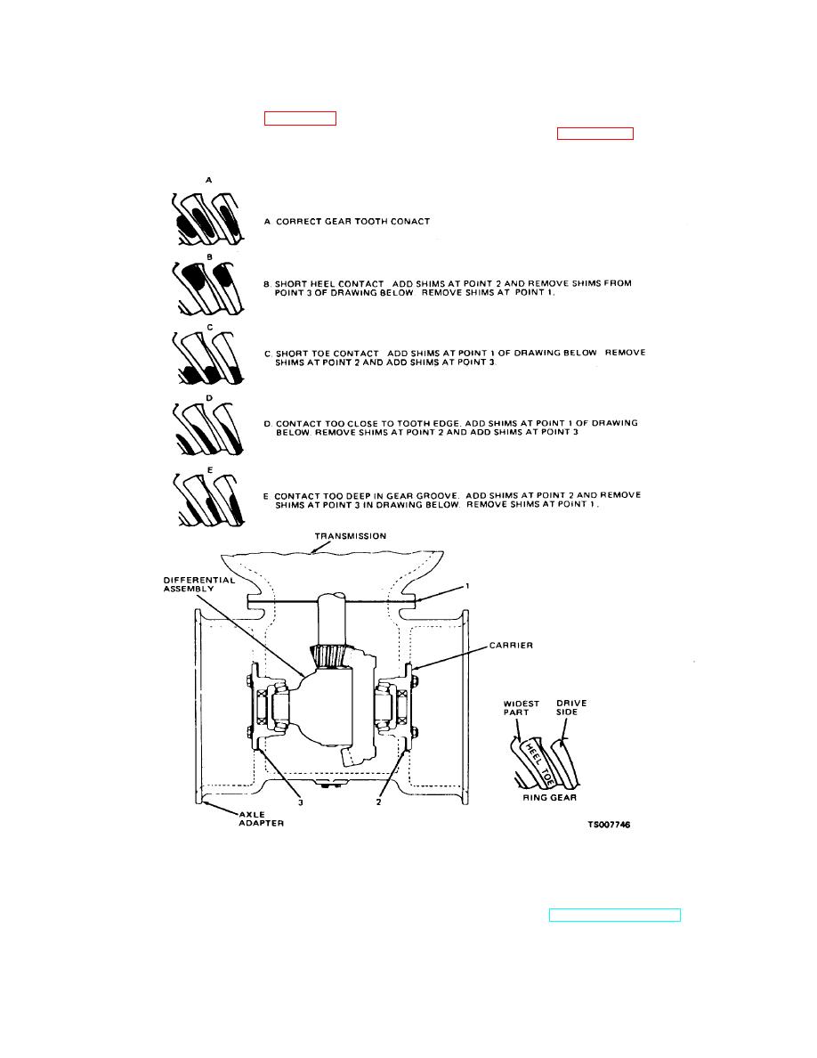
Figure 2-11. Ring Gear and Pinion Tooth Contact Patterns. |
|
||
| ||||||||||
|
|
 TM 10-3930-632-34
b.
Installation.
Rotate the pinion drive gear until the ring gear makes
one complete revolution. Remove the axle adapter, note
(1) Install the assembled axle adapter and
the area of tooth contact on the ring gear and compare it
differential on the truck as shown in figure 2-10. Tighten
with that shown in figure 2-11. Make adjustments as
the mounting bolts to 40 to 60 ft/lbs.
indicated in the illustration to correct faulty gear wear
(2) Paint three or four teeth of the gear of the
patterns.
pinion drive shaft with red lead or mechanic's blue.
Figure 2-11. Ring Gear and Pinion Tooth Contact Patterns.
(3) Install the wheel and axle ends (TM 10-3930-
(5) Replace brake line tee and brake lines removed
632-12).
during disassembly (TM 10-3930-632-12).
(4) Remove the engine and transmission supports;
(6) Fill the differential and transmission (LO 10-
lower the fork lift truck to the floor.
3930-632-12).
2-17
|
|
Privacy Statement - Press Release - Copyright Information. - Contact Us |
