 |
|||
|
|
|||
|
|
|||
| ||||||||||
|
|
 TM 10-3930-631-34
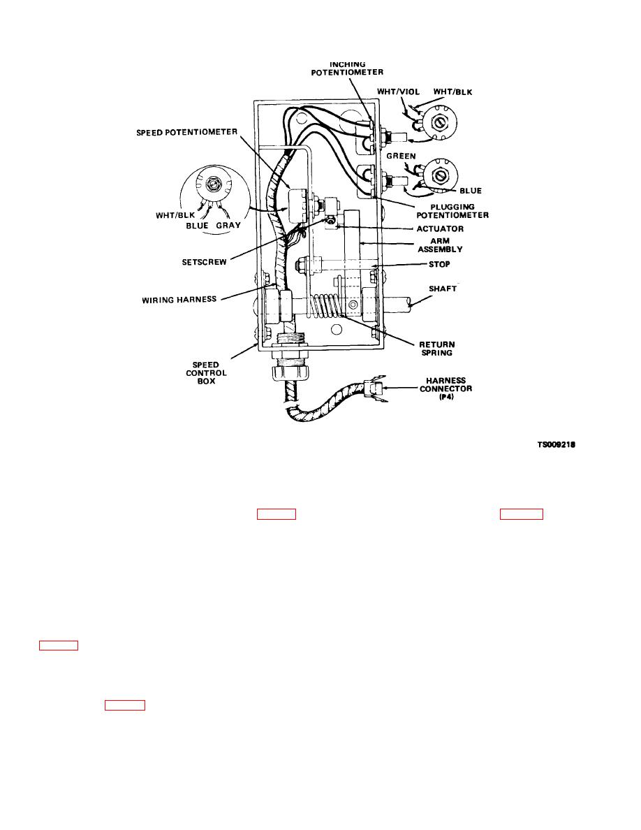
Figure 9-3. Accelerator control.
(2) As the accelerator is depressed it in-
d. Contactor Panel
creases resistance in the speed potentiometer (fig. 9-3).
(1) The contactor panel (fig. 2-7) is mounted
This action results in an increased voltage to the drive
on the frame below and to the left of the seat. Wiring
motor and increases speed of the truck. Decreasing the
harness circuits are connected to terminals on the
amount of pressure on the accelerator lowers the voltage
bottom of the contactor box.
and decreases speed
of truck.
Releasing the
(2) Electrical contactors in the panel control
accelerator completely halts current flow to drive motor.
operation of the drive motor, hydraulic pump motor and
(3) If the truck is moving and the accelerator is
emergency cutout. When the forward and reverse
released and the direction of travel is reversed, a
control contacts are set in the F (forward) position,
plugging mode is required to supply retarding torque for
current flows through the
closed key, seat and
deceleration. The severity of the plugging action on the
emergency cutout switches, through the forward and
motor can be adjusted with the plugging potentiometer
reverse switch to the contactor panel and through
contactor coil. From the contactor panel it flows to the
(4) An inching control is built into the ac-
static panel control circuit module and back to the
celerator. By slightly depressing the accelerator the
battery negative post.
operator can slowly inch the truck into position. The
(3) When a forward or reverse contactor coil is
inching speed can be adjusted through the inching
energized, the circuits to the speed and inching
potentiometer (fig. 9-3).
potentiometers are closed. Current also flows
9-4
|
|
Privacy Statement - Press Release - Copyright Information. - Contact Us |
