 |
|||
|
|
|||
|
|
|||
| ||||||||||
|
|
 TM 10-3930-631-34
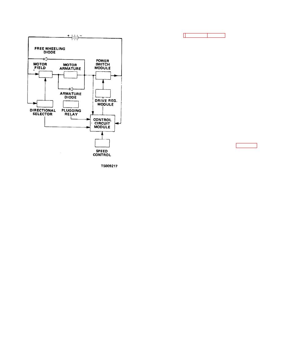
locate and describe the main components of the drive
control. Refer to figures 9-1 and 9-2 for further clarity
and interconnection of the components.
b. Forward and Reverse Control.
(1) The forward and reverse control is mounted
beneath the instrument panel. A shaft extending from
the top of the control is connected to the forward and
reverse control lever.
(2) The control lever has three positions F
(forward), N (neutral) and R (reverse). Movement of the
lever to F (forward) position sets the contact fingers in
the control to deliver current flow to the motor to drive
the truck forward.
(3) In N (neutral) the current flow is halted and
the drive motor cannot operate.
(4) In R (reverse) the contact fingers are set to
deliver current to the drive motor to rotate the differential
for reverse movement of the truck.
(5) When the drive motor is actuated the
hourmeter mounted on the instrument panel operates.
The meter records operating time of the truck.
c. Accelerator Control.
(1) The accelerator control (fig.
9-3) is
mounted below the instrument panel. A foot pedal or
accelerator is connected to the accelerator control
through a linkage.
Figure 9-2. Block diagram.
9-2. Drive Control Components
a. Description. The following paragraphs
9-3
|
|
Privacy Statement - Press Release - Copyright Information. - Contact Us |
