 |
|||
|
|
|||
|
Page Title:
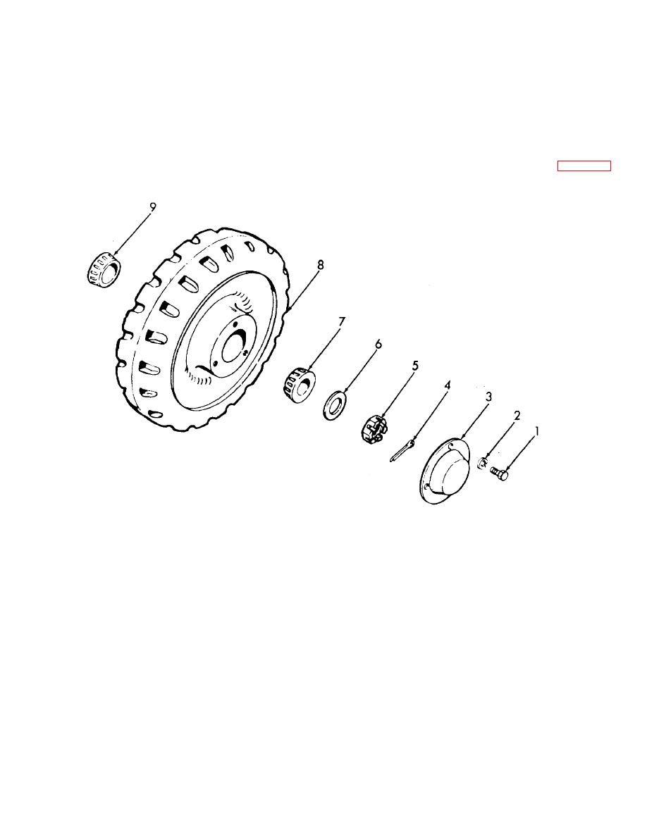
Figure 4-25. Rear wheel, exploded view. |
|
||
| ||||||||||
|
|
 TM 10-3930-631-12
outer wheel bearing (7) on spindle and inside wheel.
evident.
tapered side in.
(6) Install cotter pin (4) to secure nut.
(4) Install wheel nut (5) and washer (6) on
(7) Install hub cap (3) and secure with three
spindle. Tighten nut and as nut is tightened rotate wheel
screws (I) and lock washers (2).
under power. Elevate truck. Block other wheel to
(8) Tilt mast backward to lower wheel to
prevent turning. Continue tightening nut until heavy drag
floor. Remove block from under mast.
is felt while rotating wheel. Tighten nut to 50 foot-
e. Rear Wheel Removal. Use a suitable jack and
pounds.
raise rear of truck until wheels clear the floor. Block front
(5) Slowly loosen nut to aline cotter pin hole.
wheel to prevent truck from rolling. Refer to figure 4-25
Be sure wheel rotates freely and no bearing end play is
and remove rear wheel as follows:
1.
Screw
2.
Lock washer
3.
Hub cap
4.
Cotter pin
5.
Wheel nut
6.
Washer
7.
Outer wheel bearing
8.
Wheel and tire assembly
9.
Inner wheel bearing
Figure 4-25. Rear wheel, exploded view.
(1) Remove three screws (1) and lock
(3) Remove outer wheel bearing (7) and
washers (2) and remove hub cap (3).
wheel assembly (8) from axle spindle.
(2) Remove cotter pin (4) from wheel nut (5)
(4) Remove inner wheel bearing (9).
and remove wheel nut and washer (6).
4-30
|
|
Privacy Statement - Press Release - Copyright Information. - Contact Us |
