 |
|||
|
|
|||
|
Page Title:
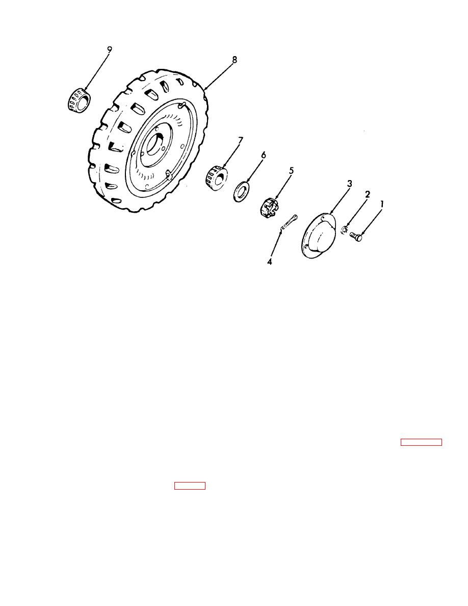
Figure 4-24. Drive wheel, exploded view. |
|
||
| ||||||||||
|
|
 TM 10-3930-631-12
1.
Screw
2.
Lock washer
3.
Hub cap
4.
Cotter pin
5.
Wheel nut
6.
Washer
7.
Outer wheel bearing
8.
Wheel and tire assembly
9.
Inner wheel bearing
Figure 4-24. Drive wheel, exploded view.
(a) Remove three screws (1) and lock
(2) Inspect brake drum for cracks, flat
washers (2) and remove hub cap (3).
spots, excessive wear, and damage.
(b) Remove cotter pin (4) from wheel nut (5)
(3) Inspect bearings (7 and 9) and bearing
and remove wheel nut and washer (6) from axle.
cups in wheel for wear or damage.
(c) Remove outer wheel bearing (7) from
(4) Clean bearings and bearing surfaces
wheel and axle.
with cleaning compound, solvent (Fed. Spec. P-D-680).
(d) Remove wheel assembly (8). Remove
d. Front Wheel Installation. Refer to figure 4-24
wheel carefully to prevent damage to brake shoes or
and install the wheel assembly as follows:
drums.
(1) Repack the outer and inner bearings (7
(e) Remove inner wheel gearing (9).
and 9) with grease (GAA).
c. Inspection.
(2) Install inner bearing (9) on axle spindle,
(1) Inspect wheel and tire (8, fig. 4-24) for
with tapered side out.
damage. Check teeth on ring or bull gear inside wheel
(3) Install wheel assembly (8) on bearing
for damage.
and spindle. Hold wheel assembly in place and install
4-29
|
|
Privacy Statement - Press Release - Copyright Information. - Contact Us |
