 |
|||
|
|
|||
|
Page Title:
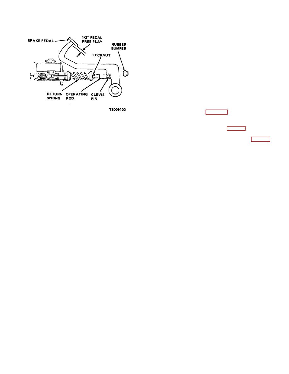
Figure 4-18. Service brake pedal adjustment. |
|
||
| ||||||||||
|
|
 TM 10-3930-631-12
clevis to bring pedal travel to correct limits.
(4) Connect clevis to brake pedal and
secure with clevis pin and cotter pin. Check pedal travel.
Adjust as above if necessary to bring travel within limits
specified.
(6) A rubber bumper mounted in front of the
brake pedal arm stops forward progress of pedal. If
necessary to obtain correct pedal travel as above, screw
bumper in or out of the bracket to allow pedal movement.
4-33. Service Brake Master Cylinder
a. Inspection. Remove floor and toe plates.
Inspect master cylinder for leaks, damage and proper
fluid level.
Replace master cylinder if leaking or
damaged.
b. Removal.
(1) Refer to figure 4-6 and remove stoplight
and interlock switches and disconnect brake line from
Figure 4-18. Service brake pedal adjustment.
master cylinder.
(2) Disconnect clevis (fig. 4-18) from brake
(1) Slowly depress brake pedal and check
11 pedal.
free travel. Observe push rod action at master cylinder.
(3) Remove mounting screws (1, fig. 4-19),
(2) If free travel is more or less than one-
lock washers (2), and nuts (3). Remove master cylinder
half inch, remove cotter pin and clevis pin and
(4) from truck.
disconnect clevis from pedal.
(3) Loosen lock nut on clevis and adjust
4-24
|
|
Privacy Statement - Press Release - Copyright Information. - Contact Us |
