 |
|||
|
|
|||
|
Page Title:
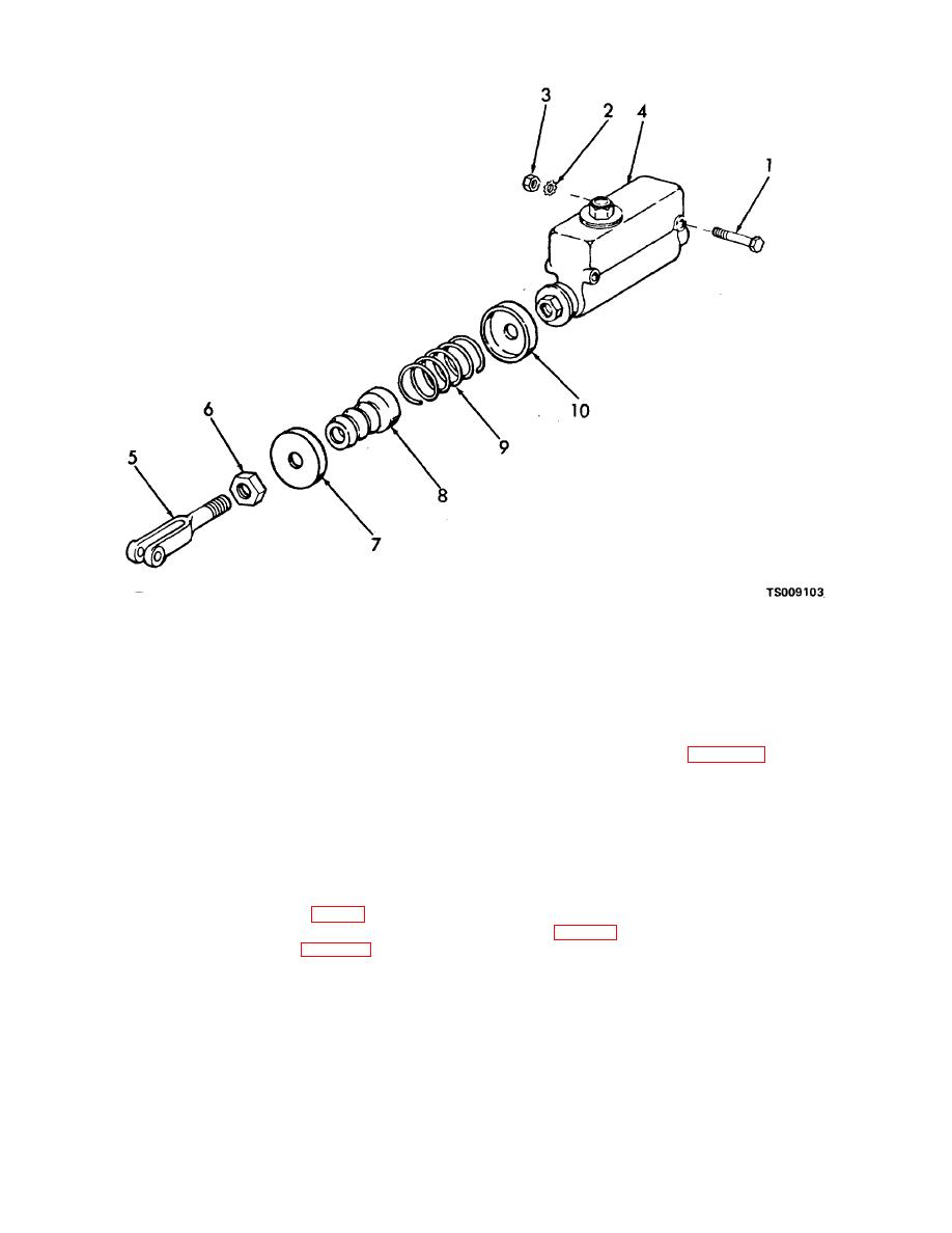
Figure 4-19. Service brake master cylinder, exploded view. |
|
||
| ||||||||||
|
|
 TM 10-3930-631-12
1.
Screw
6.
Nut
2.
Lock washer
7.
Spring retainer
3.
Nut
8.
Boot
4.
Master cylinder
9.
Return spring
5.
Clevis
10.
Spring retainer
Figure 4-19. Service brake master cylinder, exploded view.
(4) Remove nut (6) and clevis (5) and
pedal. Adjust pedal travel (para 4-32) as necessary.
remove spring retainers (7) and (10), boot (8) and return
(5) Refer to d. below to fill master cylinder
spring (9) from master cylinder.
and bleed brake hydraulic system.
c. Installation.
d. Bleeding Brake Hydraulic System. Each time
(1) Install spring retainers (7 and 10, fig. 4-
the system has been drained or refilled or a part has
19), return spring (9), nut (6) and clevis (5) on master
been disconnected or replaced, the system must be bled
cylinder (4).
as follows:
(2) Install master cylinder on truck and
(1) Remove filler cap from master cylinder
secure with screws (1), lock washers (2) and nuts (3).
and fill to proper level (3/8 to 1/2 inch from top).
(3) Connect brake line (fig. 4-5) and install
(2) Connect a bleeder hose to bleeder
brake interlock and stoplight switches on master cylinder.
screw (fig. 4-20) on front wheel. Submerge other end of
(4) Connect clevis (fig. 4-18) to brake
hose in a glass jar filled with brake fluid.
4-25
|
|
Privacy Statement - Press Release - Copyright Information. - Contact Us |
