 |
|||
|
|
|||
|
Page Title:
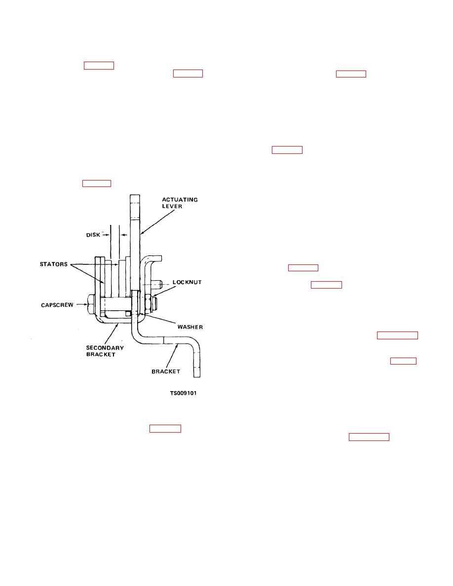
Figure 4-17. Checking brake caliper adjustment. |
|
||
| ||||||||||
|
|
 TM 10-3930-631-12
(5) Distance should be 4.50 to 4.74 inches.
position. Make certain stator pads contact disk.
(6) Remove self-locking nut, washer and
f. Brake Switch Adjustment. When the seat is
shoulder screw (fig. 4-15) to disconnect lower linkage.
occupied the seat switch must be closed to allow truck to
Loosen jam nut and adjust spring retainer (fig. 4-15) to
operate. A switch actuator (fig. 4-14) connected to the
compress spring to distance shown in (5) above.
switch linkage moves up and down to operate the switch.
Tighten jam nut to hold retainer.
Adjust actuator as follows:
(7) Thread clevis fully on bottom of rod and
(1)
With operator's seat unoccupied,
secure with jam nut.
actuator must move down and depress switch arm and
(8) Connect lower clevis to brake caliper
open switch contacts.
with shoulder screw, flat washer and lock nut.
(2) Check across switch with continuity
e. Caliper Assembly Brake Pad Inspection and
tester to make certain switch contacts are open.
Adjustment. If caliper brake pads wear or are out of
(3) If contacts are not open, adjust switch
adjustment, adjust as follows:
bracket (fig. 4-16) by loosening mounting screws and
(1) Seat must be occupied and brake in off
raising or lowering switch until switch arm contacts
position.
actuator properly. Further adjustment is possible by
(2) Check distance between disk and pads
moving jam nuts on brake rod to raise or lower switch
on brake stator (fig. 4-17).
actuator to achieve correct switch operation. Tighten
bracket mounting screws and jam nuts to hold
adjustment.
(4) With seat occupied, switch arm should
move away from switch as actuator rises. Check switch
with continuity tester, to be certain switch contacts are
closed.
g. Adjustment Check. Check adjustment as
follows:
(1) Connect battery receptacle and prepare
truck to travel (para 2-4).
(2) With operator in seat and key switch on,
place truck in motion (para 2-7).
(3) Remove weight from seat to apply
parking brake. Truck should stop and remain stationery
on a 15 degree incline.
(4) Install drip pan, floor and toe plates and
sheet metal cover.
h. Switch Replacement. Refer to figure 4-14 to
replace seat switch.
4-32. Service Brake Linkage
a. General. The service brake pedal (fig. 2-1) is
connected to the master cylinder by a clevis attached to
the cylinder piston push rod. A spring, mounted between
two retainers on the rod, returns the pedal to released
position.
b. Adjustment. Pedal free play should be adjusted
to one-half inch of travel to allow master cylinder to
Figure 4-17. Checking brake caliper adjustment.
return to off position and reduce useable length of stroke.
Remove floor and toe plates to gain access to master
(3) Tighten lock nuts (fig. 4-17) to more
cylinder and linkage. Refer to figure 4-18 and adjust
stator pads closer to disk. Tighten nuts until disk almost
service brake pedal travel as follows:
makes contact with stator pads. Disk should move freely
between pads.
(4) Release seat to place brake in park
4-23
|
|
Privacy Statement - Press Release - Copyright Information. - Contact Us |
