 |
|||
|
|
|||
|
Page Title:
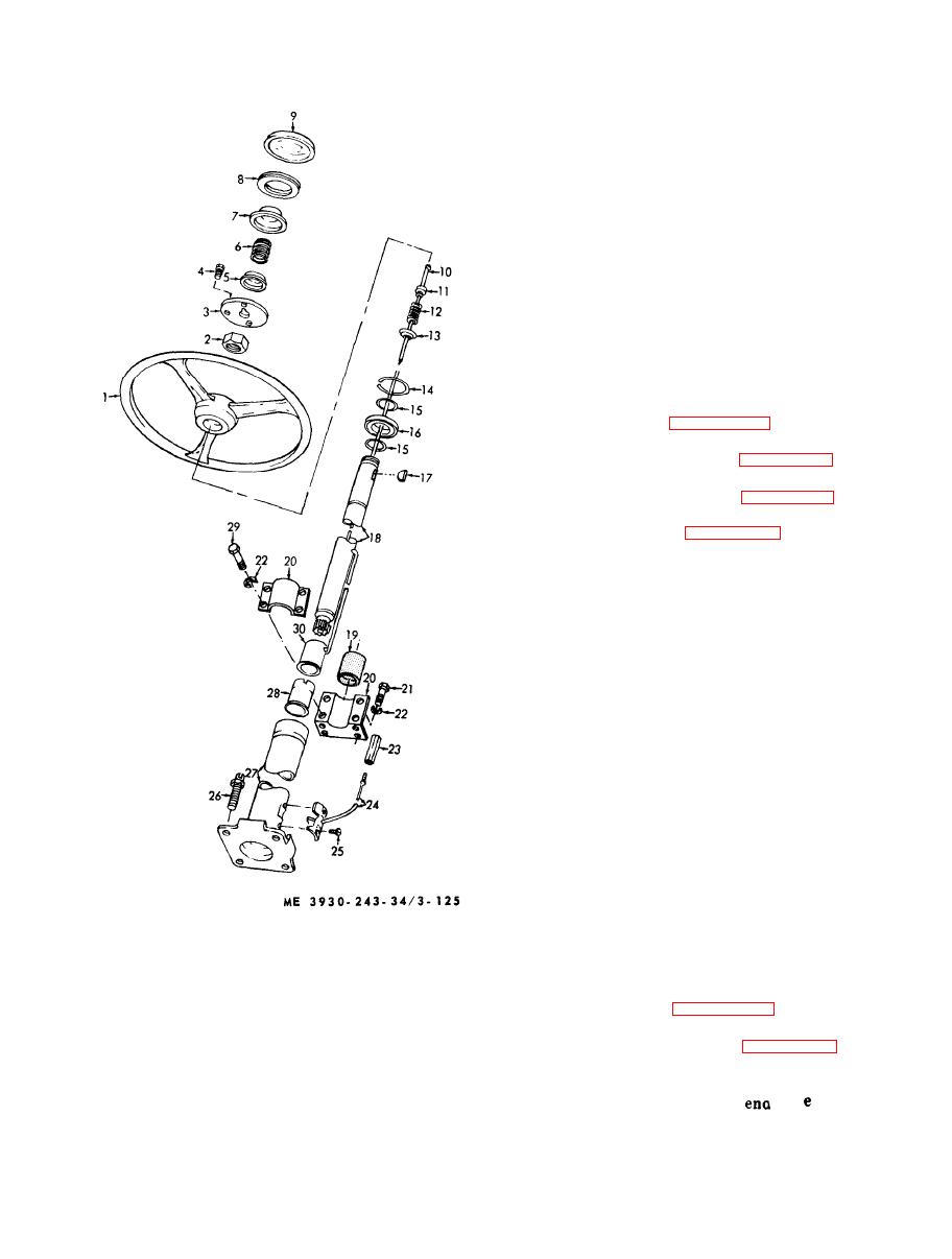
Figure 3-125. Steering column, disassembly and reassembly. |
|
||
| ||||||||||
|
|
 3-61. Steering System Accumulator
a. General. The accumulator is provided to store
e n e r g y for a limited time to the power steering in
c a s e of engine failure. The accumulator is charged
with nitrogen and hydraulic oil under high
p r e s s u r e . It is located behind the operator's access
ladder panel. The steering system accumulator is
m o u n t e d next to the brake system accumulator and
removal,
and
in
construction,
is
identical
disassembly.
WARNING
Bleed all pressure from the steering
system with the engine stopped.
Carefully open bleed valve. Failure to
bleed pressure from accumulator before
performing maintenance function may
result in damage to equipment and
serious injury to personnel.
steering system accumulator.
disassemble steering system accumulator.
reassemble steering system accumulator.
steering system accumulator.
f. Charging the Accumulator. Exercise caution
when testing or charging accumulator.
WARNING
Use only dry nitrogen gas. Bleed all
pressure as described above. Failure to
d o so could result in serious damage to
equipment and injury to personnel.
( 1 ) Remove screw and remove protector strap.
(2) Attach charging kit to accumulator gas
valve assembly.
( 3 ) Open accumulator valve to read pressure.
( 4 ) Open valve on nitrogen bottle and charge
accumulator cylinder to 900 psi.
(5) Close nitrogen bottle valve and detach
charging kit.
(6) Replace protector strap.
3-62. Tie Rods
a . G e n e r a l . The tie rod is of a three piece con-
s t r u c t i o n consisting of the rod and two tie rod end
16 Bearing
1 Steering wheel
y o k e s . The rod is screwed into the threaded yokes
2 Nut
17 Key
a n d are locked in place by tightening the bolt and
18 Shaft
3 Cap
nut. Right and left hand threads on the rod end
19 Hose
4 Screw
provide for toe in adjustment.
20 Bracket
5 Cup
6 Spring
21 Screw
7 Cap
2 2 Washer
the tie rod and tie rod end yokes.
2 3 Brush
8 Horn button
9 Cap
24 Wire
disassemble the tie rod assembly.
10 Terminal wire
25 Screw
d. Inspection.
11 Insulator
26 Screw
(8) for
12 Spring
2 7 Tube
( 1 ) Inspect rod (6) and rod
13 Washer
28 Insulator
stripped threads.
29 Screw
14 Ring
(2) Inspect rod for bend or damage
15 Ring
30 Contact ring
|
|
Privacy Statement - Press Release - Copyright Information. - Contact Us |
