 |
|||
|
|
|||
|
Page Title:
Figure 3-114. Automatic slack adjuster, disassembly and reassembly. |
|
||
| ||||||||||
|
|
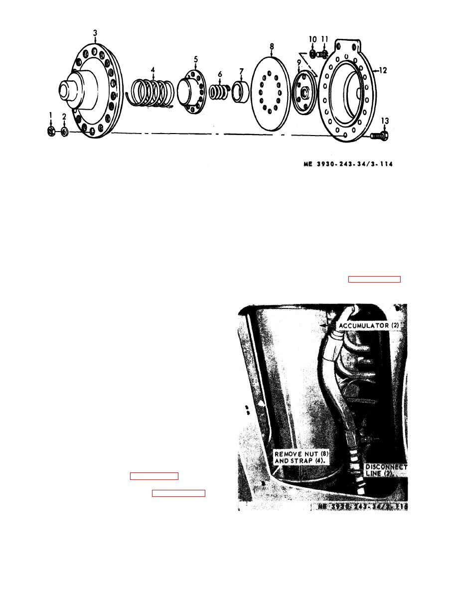 8
Diaphragm
1
Nut
9
Piston
2
Washer
10
Washer
3
Housing
11
Bolt
4
Spring
12
Cap
5
Piston
13
Bolt
6
Spring
7
Piston
(2) Inspect piston for scores and scratches.
(3) Inspect body for cracks or any damage.
a. General. The accumulator is provided to store
Replace a defective part.
e n e r g y for a limited number of brake applications
e . R e a s s e m b l y . Refer to figure 3-116 and
i n case the engine stops running. The accumulator
reassemble hydraulic brake accumulator.
cylinder has a free riding piston. Nitrogen is in-
troduced through a valve on one end of cylinder
and at the opposite end of cylinder, oil from the
h y d r a u l i c system enters cylinder forcing the piston
toward the nitrogen, compressing it to ap-
p r o x i m a t e l y 1,300 psi. The accumulator is located
behing the operator's access ladder panel.
WARNING
B l e e d the brake system pressure by
repeated application of the brakes with
t h e e n g i n e stopped, u n t i l t h e l o w
pressure warning buzzer sounds.
Continue to apply brakes several times
to further reduce accumulator pressure.
C a r e f u l l y open bleed valves at each
a u t o m a t i c slack adjuster to bleed off
pressure. F a i l u r e t o b l e e d p r e s s u r e
from brake system before servicing or
p e r f o r m i n g maintenance function may
result in damage to equipment and
s e r i o u s injury to personnel.
the hydraulic brake accumulator.
disassemble the hydraulic brake accumulator.
d. Inspection.
(1) Inspect tubing and connectors for cracks or
damage.
accumulators, removal and installation.
|
|
Privacy Statement - Press Release - Copyright Information. - Contact Us |
