 |
|||
|
|
|||
|
Page Title:
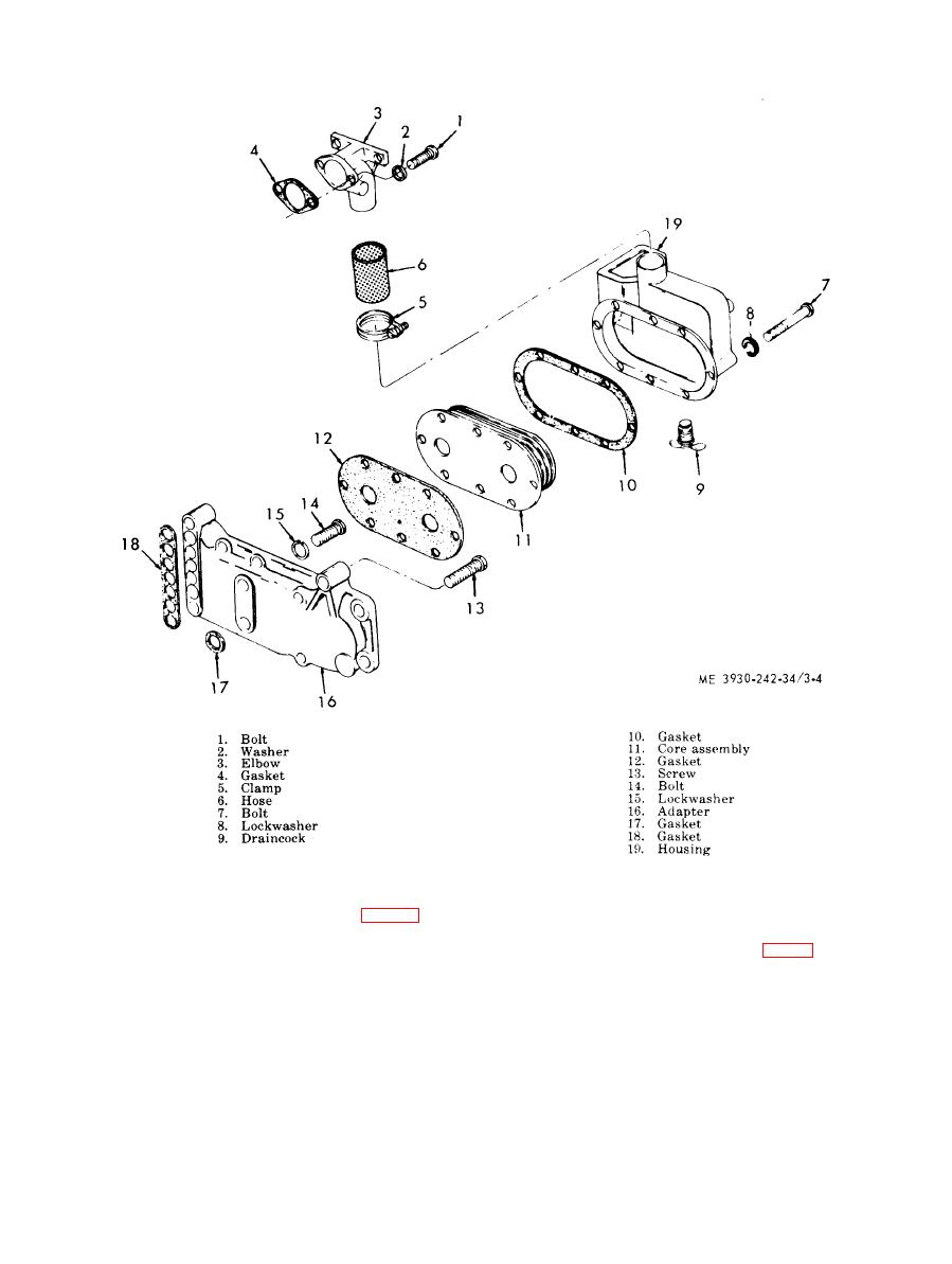
Figure 3-4. Oil cooler, disassembly and reassembly. |
|
||
| ||||||||||
|
|
 TM 10-3930-242-34
NOTE
(1) Install retainer spring (21, fig. 3-7), re-
Effective with engines serial Nos. 42D-A036 and
tainer (20) (disked side up), O-ring (19) and seal
up, the blower end plates (10 and 17, fig. 3-7) are
washer (18) on the rotor shafts (22 and 23).
counterbored and use two teflon oil seals in each
(2) Place front end plate (10) on two wood
end plate in lieu of washer (18), O-ring (19), re-
b l o c k s ; then install the rotors, gear up, on the
tainer (20), and spring (21). The two teflon seals
end plate.
are pressed into the counterbore of the end plates
prior to reassembly.
NOTE
( 3 ) Install a retainer spring (21), retainer
To prevent inadequate lubrication or low oil pres-
sure, care must be exercised in the assembly of
(20), O-ring (19), and seal (18) on rotor shaft in
the front (10) and rear (17) end plates. The rear
t h e gear end of both rotors and install blower
end plate (17) does not have tapped holes for
housing (25) over the rotors.
thrust washer plate bolt (6) and no thrust washer
( 4 ) Place the rear end plate (17) over the
lubrication oil holes.
|
|
Privacy Statement - Press Release - Copyright Information. - Contact Us |
