 |
|||
|
|
|||
|
Page Title:
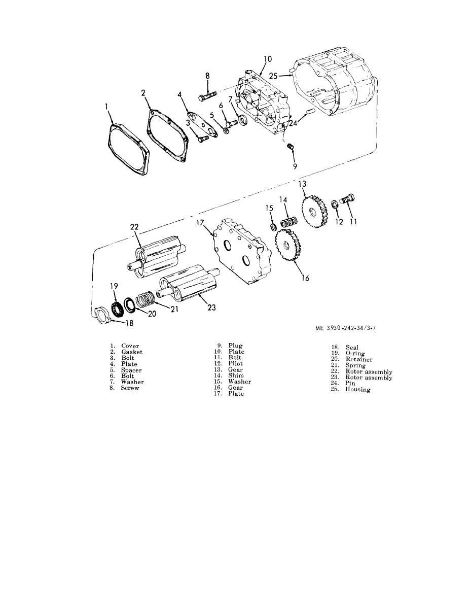
Figure 3-7. Blower, disassembly and reassembly. |
|
||
| ||||||||||
|
|
 TM 10-3930-242-34
rotor shafts. Be sure that seals are properly
tioning the rotors with missing serrations in the
positioned on rotors. Then, secure end plate (17)
u p p e r rotor facing to the left, and the missing
s e r r a t i o n in the lower rotor facing the bottom.
to blower housing with bolts.
Install the shim (14) and spacers (15) in the
( 5 ) Attach two thrust washers (7) to front
c o u n t e r b o r e in rear face of rotor gears. Place
end of blower with bolt (6).
g e a r s on end of the shafts with missing serra-
(6) Attach three spacers (5) and thrust plate
t i o n in alignment with missing serrations on
(4) to front end of blower with three bolts (3).
shaft.
Tighten bolts to 7-9 ft.-lb. torque and check the
clearance between thrust plate and thrust
( 8 ) Tap the gears lightly with a soft ham-
mer to seat the gears on the shaft. Then, rotate
w a s h e r . The clearance should be 0.001-0.003
inch.
the gears until punch marks on the face of gears
match. If the punch marks on the face of gears
( 7 ) position the rotors so that the missing
d o not match, reposition the gears.
serration on the gear end of the rotor shafts are
90 degrees apart. This is accomplished by posi-
(9) Wedge a clean cloth between the blower
|
|
Privacy Statement - Press Release - Copyright Information. - Contact Us |
