 |
|||
|
|
|||
|
|
|||
| ||||||||||
|
|
 TM 10-3930-242-34
( 2 ) Use two pullers to remove both blower
(3) Inspect springs for cracks and bends.
g e a r s from rotor shaft at the same time. Mark
( 4 ) Inspect all mounting hardware for de-
t h e upper rotor gear to facilitate identification
f e c t s and wear. Replace a defective part.
a t reassembly.
s e m b l e the air inlet housing.
d. Cleaning and Inspection.
(1) Clean the blower assembly components,
a i r inlet housing.
using a dry cleaning solvent such as P-D-680 or
equal.
3-5. Blower Assembly
( 2 ) Inspect the rotors and housing for deep
a. General. The blower assembly is located
scratches. If deep scratches exist, dress the
behind the air inlet housing. It supplies the
parts down.
f r e s h air required for combustion and scaveng-
( 3 ) Inspect the rotors for scoring.
ing. The revolving motion of the rotors provide a
(4) Check for leaking oil seals.
c o n t i n u o u s and uniform displacement of air.
(5) Check for loose or worn rotor shaft and
b. Removal.
r o t o r shaft bearings. See table 1-1 for replace-
(1) Remove
fuel
filter
(TM
the
ment standards.
10-3930-242-12).
NOTE
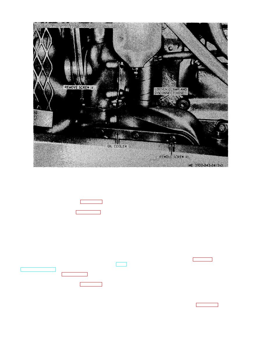
(2) Refer to figure 3-5 and remove the
Loose rotor shafts or worn rotor shaft bearings
b l o w e r assembly.
will result in contact between rotor lobes, rotor,
and end plates or rotor and housing, Excessive
s e m b l e blower assembly as follows:
backlash between blower timing gears usually re-
(1) Wedge a clean cloth between the blower
sults in rotor lobes rubbing together throughout
their entire length.
rotors to prevent their turning and remove
blower drive cam retainer and blower drive
semble as follows:
s p r i n g support to rotor gear.
|
|
Privacy Statement - Press Release - Copyright Information. - Contact Us |
