 |
|||
|
|
|||
|
Page Title:
FRONT AXLE PIVOT PIN REPLACEMENT |
|
||
| ||||||||||
|
|
 TM 10-3930-673-34
8
This Task Covers:
a. Removal
b. Installation
INITIAL SETUP
Equipment Condition
Tools and Special Tools
Frame tilt cylinder removed
Tool Kit, General Mechanic's: Automotive
(TM 10-3930-673-20)
(Item 23, Appendix D)
Shop Equipment, Automotive Maintenance,
Materials/Parts
Common No. 2 Less Power
Locknut
(Item 17, Appendix D)
Wood Blocks
Wrench, Torque 0 - 175 lb-ft (0 - 237 Nm)
(Item 28, Appendix D)
Personnel Required
Jack Stands (Item 9, Appendix D)
Two
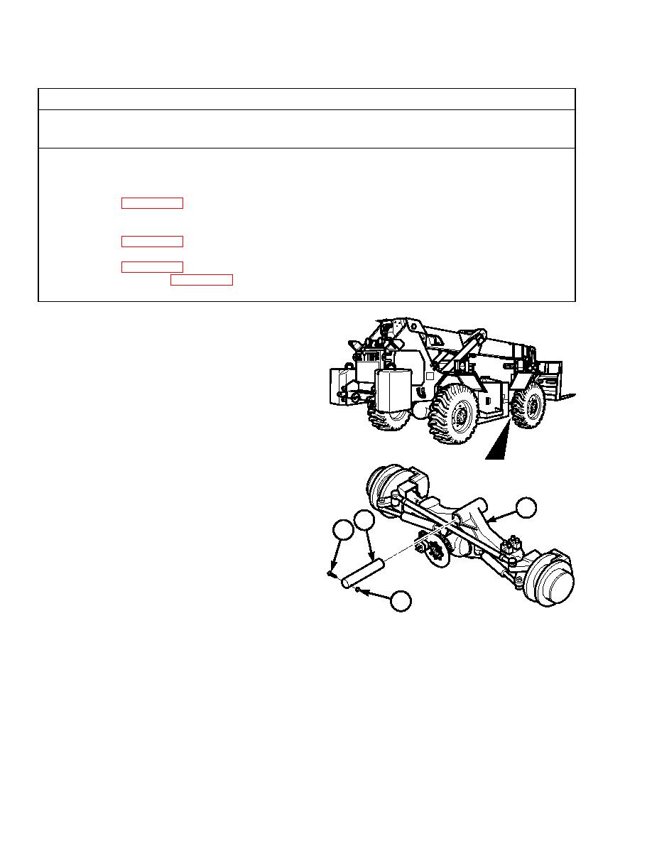
a. Removal.
(1)
Raise vehicle by the frame so that
weight of vehicle is off pivot pin (1).
Do not raise vehicle off ground.
(2)
Support vehicle under frame using
suitable stands.
(3)
Remove locknut (2) and screw (3)
from axle pivot pin (1). Discard
locknut.
TR00001
(4)
Remove axle pivot pin (1) from front
axle assembly (4).
4
b. Installation.
1
3
(1)
Install axle pivot pin (1) in front axle
assembly (4).
(2)
Install screw (3) and locknut (2) on
axle pivot pin (1). Tighten screw to
100 lb-ft (135.58 Nm).
2
(3)
Raise vehicle and remove stands.
TR00254
(4)
Lower vehicle.
NOTE
Follow-on Maintenance: Install frame tilt cylinder (TM 10-3930-660-20).
END OF TASK
|
|
Privacy Statement - Press Release - Copyright Information. - Contact Us |