 |
|||
|
|
|||
|
Page Title:
FRONT AXLE ASSEMBLY REPLACEMENT/REPAIR - continued |
|
||
| ||||||||||
|
|
 TM 10-3930-673-34
(8)
Raise floor jack until axle pivot pin hole (B) is aligned with frame pivot pin holes.
(9)
Secure front axle assembly (8) to frame with axle pivot pin (11) and washer spacers (12).
At least one washer spacer on each side of axle pivot pin hole is required.
(10)
Install screw (10) and locknut (9) on axle pivot pin (11). Tighten screw to 100 lb-ft
(135.58 Nm).
(11)
Use a floor jack to raise front of vehicle until vehicle frame clears jackstands; remove
jackstands and carefully lower vehicle.
(12)
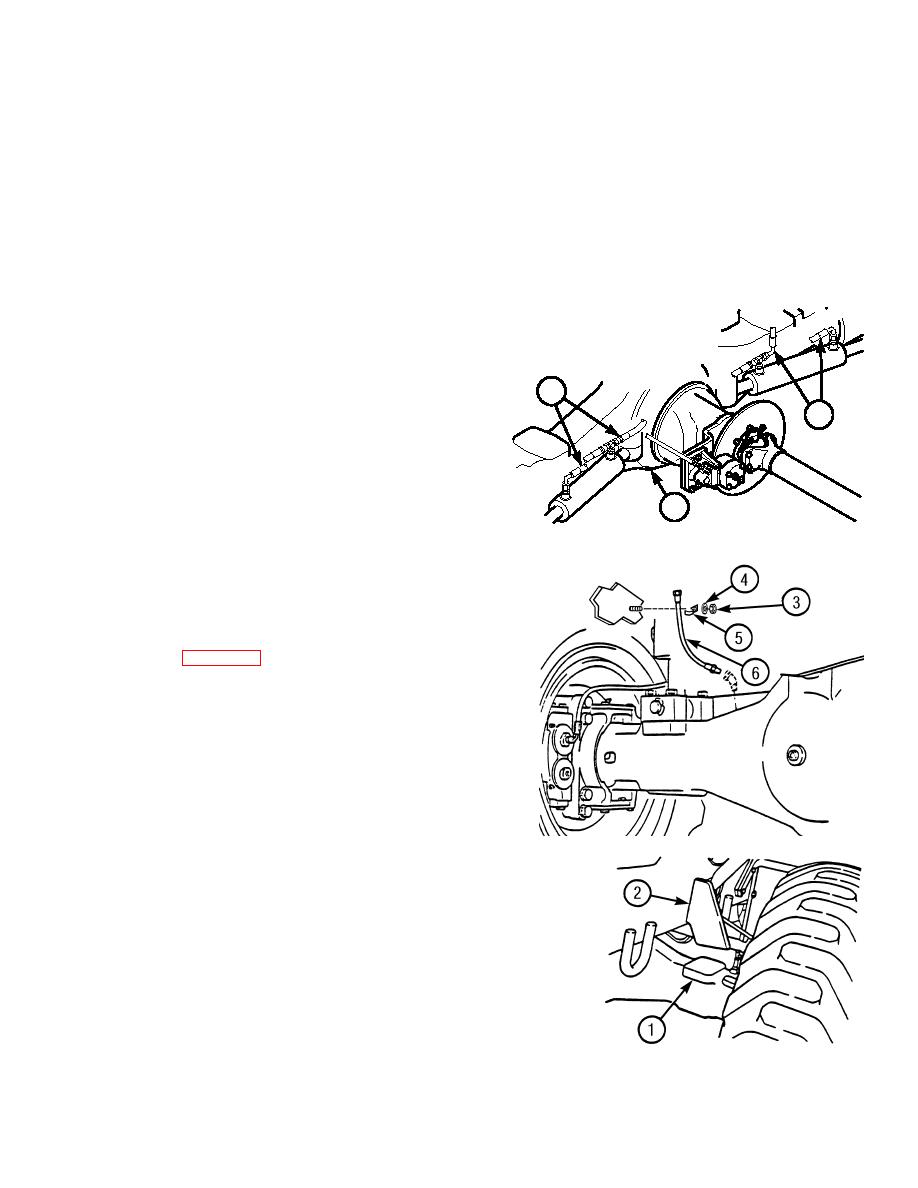
Connect front steering cylinder
hoses (7) to front axle assembly (8).
7
7
8
TR00251
(13)
Install axle breather hose (6),
clamp (5), lockwasher (4), and nut (3)
on frame.
(14)
Install front disk brake assemblies
(15)
Install frame tilt cylinder
(TM 10-3930-673-20).
(16)
Install front propeller shaft
(TM 10-3930-673-20).
(17)
Install parking brake cable
(TM 10-3930-673-20).
TR00250
(18)
Remove wood blocks from between
frame pads (1) on rear axle and
frame tilt stop pads (2).
(19)
Bleed hydraulic steering cylinders,
by rotating steering wheel five times.
TR00249
END OF TASK
8-9
|
|
Privacy Statement - Press Release - Copyright Information. - Contact Us |