 |
|||
|
|
|||
|
Page Title:
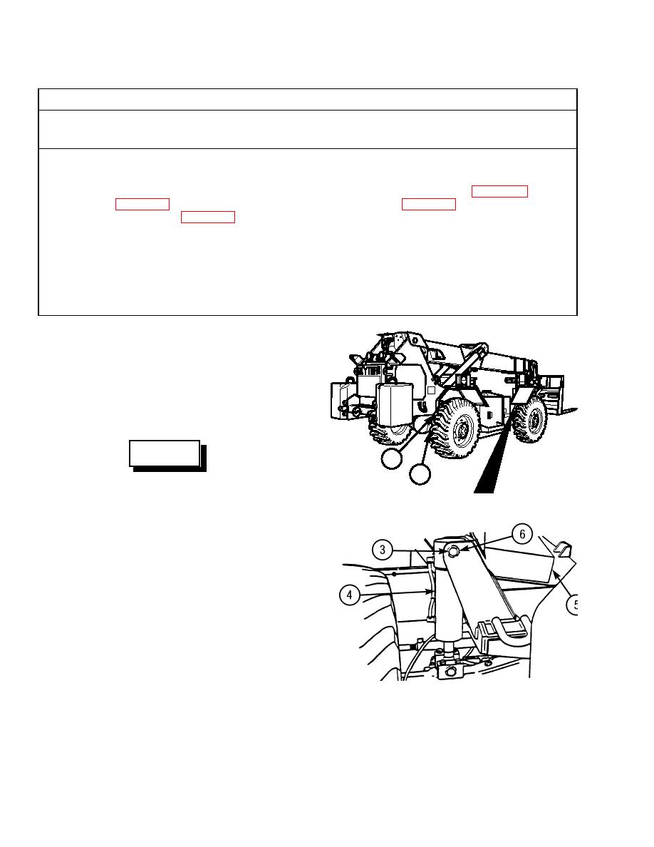
FRAME TILT CYLINDER REPLACEMENT |
|
||
| ||||||||||
|
|
 TM 10-3930-673-20-2
16
This Task Covers:
a. Removal
b. Installation
INITIAL SETUP
Materials/Parts
Tools and Special Tools
Compound, Anti-seize (Item 7, Appendix C)
Tool Kit, General Mechanic's: Automotive
Tags (Item 39, Appendix C)
(Item 18, Appendix F)
Lockwashers (4)
Cap and Plug Set (Item 3, Appendix F)
Wood Blocks
Equipment Condition
Personnel Required
Wheels chocked
Two
Vehicle leveled (TM 10-3930-673-10)
References
TM 10-3930-673-10
a. Removal.
(1)
Position wood blocks between both rear
frame tilt stop pads (1) on rear axle (2).
(2)
Remove base pivot pin (3) from frame tilt
cylinder (4) and vehicle frame (5).
WARNING
1
2
Use care when removing snap and
retaining rings. Snap and retaining rings
TR00585
are under spring tension and can act as
projectiles when released and could cause
severe eye injury.
(a)
Remove retaining ring (6) from base pivot
pin (3).
(b)
With aid of assistant, support frame tilt
cylinder (4) and remove base pivot pin
(3).
(3)
Retract frame tilt cylinder (4).
(a)
Start engine (TM 10-3930-673-10) and
retract frame tilt cylinder (4) by moving
TR00508
frame control joystick to right.
(b)
Shut off engine (TM 10-3930-673-10).
|
|
Privacy Statement - Press Release - Copyright Information. - Contact Us |
