 |
|||
|
|
|||
|
|
|||
| ||||||||||
|
|
 TM 10-3930-673-20-2
(1)
Prepare and set up in-line flowmeter for
testing.
(2)
Make hydraulic connections to flowmeter.
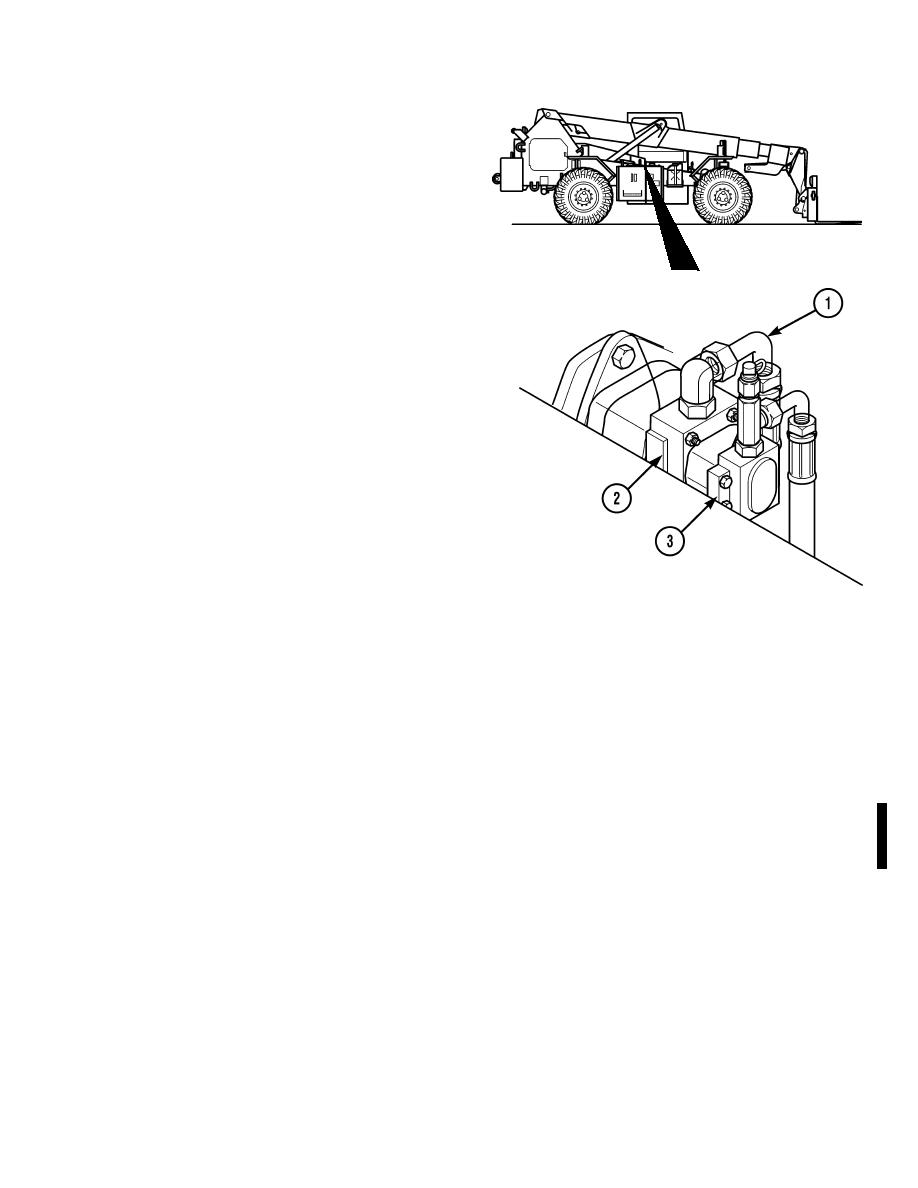
(a)
Tag, mark, and disconnect pump outlet
hose (1) from pump section being
TR00003
tested.
(b)
Connect test hose from outlet side of
section being tested to inlet port of
flowmeter.
(c)
Connect hydraulic hose (1) removed in
Step (2)(a) above to outlet port of
flowmeter.
NOTE
Hydraulic pumps are tested at specific
engine RPMs. STE/ICE kit may be used
to monitor engine speed.
(3)
Start engine (TM 10-3930-673-10).
(4)
If large pump section (2) is being tested,
adjust engine speed to 2500 RPM and
pressure to 2500 PSI (17237.5 kPa). Read
TR00877
flow in GPM.
(5)
If small pump section (3) is being tested, adjust engine speed to 1800 RPM and pressure to 2500 PSI
(17237.5 kPa). Read flow in GPM.
NOTE
Hydraulic pump sections must meet following specifications:
Large pump section - 47.0-55.0 GPM @ 2500 RPM.
Small pump section - 14.6-16.9 GPM @ 2500 RPM.
If either section fails to meet or exceed specifications, replace pump. Refer to b. Removal and
(6)
c. Installation for pump replacement instructions.
(7)
Turn engine off (TM 10-3930-673-10) and allow hydraulic system to cool down before proceeding.
(8)
Disconnect test hose from outlet side of section tested and inlet port of flowmeter.
(9)
Disconnect hydraulic hose (1) from outlet port of flowmeter and connect hose to outlet side of section
tested.
Change 1
18-7
|
|
Privacy Statement - Press Release - Copyright Information. - Contact Us |
