 |
|||
|
|
|||
|
|
|||
| ||||||||||
|
|
 TM 10-3930-660-24-2
FRAME TILT CYLINDER MAINTENANCE - CONTINUED
0306 00
ASSEMBLY - CONTINUED
NOTE
Place rod and piston assembly on suitable supports to prevent damage during assembly.
8.
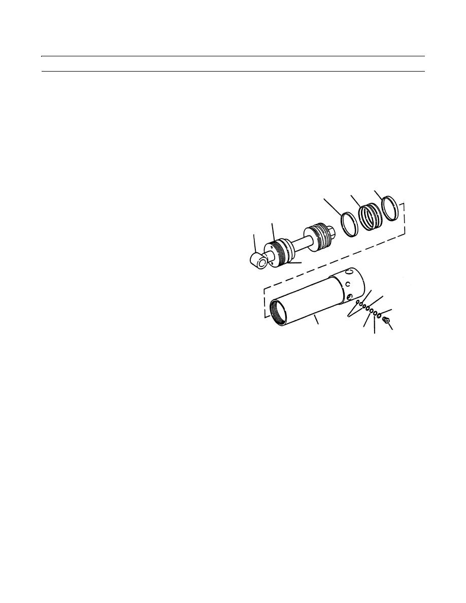
Install two new wear rings (12) and one new seal (13). Position new wear rings so that gaps are 180 degrees apart.
CAUTION
Use care when installing rod and piston assembly. Keep rod in line with cylinder tube to prevent binding.
Failure to follow this precaution will cause part damage.
9.
Lubricate cylinder tube (10) inner diameter, piston
12
13
12
(15) outside diameter and gland (9) outside diameter
with clean lubricating oil.
10.
Position rod (8) and piston assembly in cylinder tube
9
(10).
8
11
5
3
2
4
10
6
1
7
409-1389
NOTE
Tighten gland so that it is flush with end of cylinder tube. Do not overtighten gland.
11.
Tighten gland (9) onto cylinder tube (10).
12.
Install new back-up rings (2 and 3), two new back-up rings (4) and three new O-rings (5 thru 7) on each counterbalance
valve (1).
Install two counterbalance valves (1) in cylinder tube (10) as noted during Disassembly.
13.
14.
Install frame tilt cylinder (WP 0183 00).
15.
Operate equipment, check for leaks and proper operation (TM 10-3930-660-10).
END OF WORK PACKAGE
0306 00-5
|
|
Privacy Statement - Press Release - Copyright Information. - Contact Us |