 |
|||
|
|
|||
|
|
|||
| ||||||||||
|
|
 TM 10-3930-660-24-2
REAR DIFFERENTIAL CARRIER ASSEMBLY MAINTENANCE - CONTINUED
0298 00
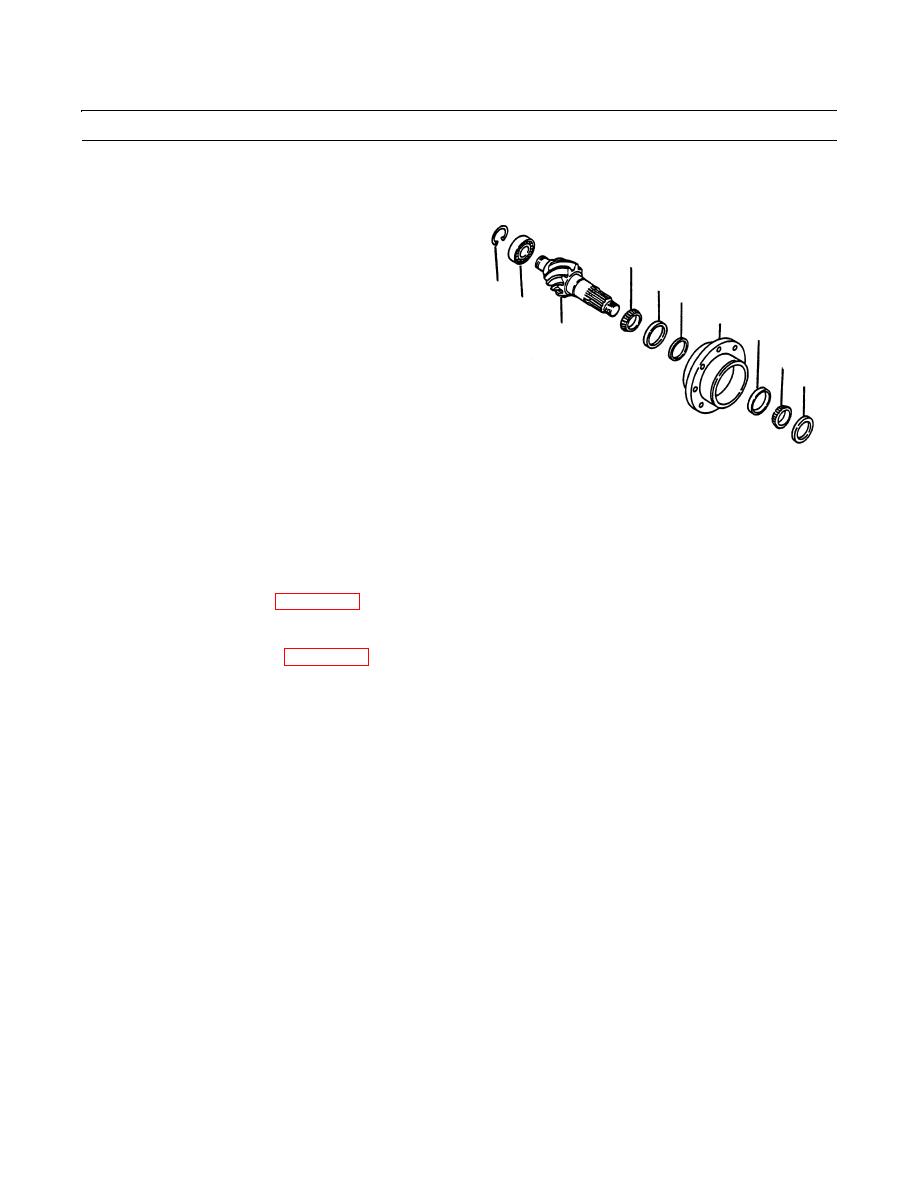
DISASSEMBLY - CONTINUED
19.
Remove pinion bearing cage thrust washer (30).
20.
Place bevel pinion (26) and bearing cage (27) in a
press with splined end of pinion at the top of assembly.
32
21.
Support bearing cage (27) under flange area with
34
blocks.
33
36
37
27
22.
Use a press to remove bevel pinion (26) from bearing
35
cage (27).
26
31
23.
Remove outer bearing cone (31) from bearing cage
30
(27).
24.
Use puller and remove inner bearing cone (32) and
bearing spacer (33) from bevel pinion (26).
25.
Use puller to remove inner bearing cup (34) and outer
409-1287
bearing cup (35) from bearing cage (27).
26.
Install a soft metal cover over vise jaws to protect bevel pinion (26). Place bevel pinion in a vise.
27.
Remove snap ring (36) from end of bevel pinion (26).
28.
Remove bearing (37) from spigot end of bevel pinion (26).
CLEANING
See Cleaning instructions (WP 0316 00).
INSPECTION
See Inspection instructions (WP 0317 00).
ASSEMBLY
NOTE
Pinion and ring gears are a matched set. If replacement of ring gear or pinion gear is necessary, replace both
gears as a set.
1.
Use a press and suitable driver to install inner bearing cup (34) and outer bearing cup (35) into bearing cage (27). Be
sure bearing cups are tight against bottom of cage bore.
2.
Use a press and suitable sleeve driver to install inner bearing cone (34) on bevel pinion (26).
3.
If necessary, use a press and suitable sleeve driver to install spigot bearing (37) onto spigot end of bevel pinion (26).
4.
Install snap ring (36) into groove on end of bevel pinion (26).
5.
Apply a thin film of clean lubricating oil to inner and outer bearing cups (34 and 35) and bearing cones (31 and 32).
6.
Install bearing spacer (33) on bevel pinion against inner bearing cone (32).
7.
Install bevel pinion (29) and bearing assembly into bearing cage.
8.
Use a press and suitable sleeve driver and install outer bearing cone (31) on bevel pinion tight against bearing spacer
(27).
9.
Install pinion bearing thrust washer (30).
10.
Install companion yoke (23), nut (21) and washer (22) on bevel pinion (26). If necessary, use a press to push yoke on
pinion. Companion yoke (23) must be against thrust washer (30).
0298 00-4
|
|
Privacy Statement - Press Release - Copyright Information. - Contact Us |
