 |
|||
|
|
|||
|
|
|||
| ||||||||||
|
|
 TM 10-3930-660-24-2
STARTER ASSEMBLY MAINTENANCE (152 HP) - CONTINUED
0286 00
INSPECTION - CONTINUED
9.
Repeat check for all commutator bars (A) by moving one ohmmeter lead at a time. There must be continuity between
each pair of bars.
ASSEMBLY
1.
If removed, install bearing (50), wick (52), plug (51) and pin (49).
2.
Soak wick (52) and surface of bearing (50) in clean lubricating oil.
3.
Press bearing (50) into bore until even with end of drive housing (10).
4.
Install wick (52) and plug (51).
5.
Install pin (49).
6.
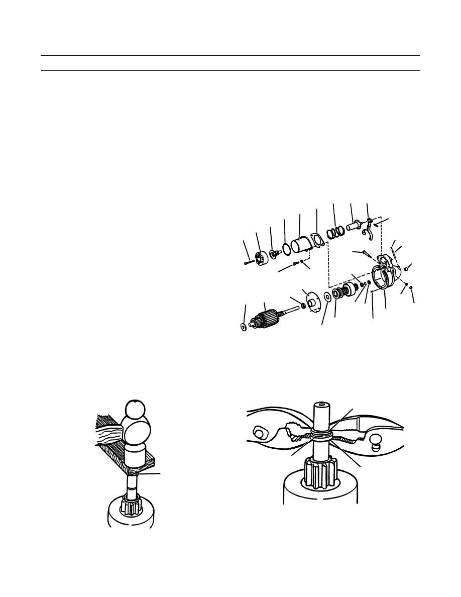
If removed, press center bearing (48) into center bear-
35 39
33
32
ing retainer (41) until flush with front face of retainer.
28
27
34
7.
Install center bearing retainer (41), washer (43) and
29
motor drive (44) on armature shaft.
26
25
51
52
36
50
46
30
31
41
48
9
42
38
47 45
37
10
44
49
43
409-1108
8.
Install pinion stop (46) (cupped side facing out) and retaining ring (47) on armature shaft. Retaining ring (47) may have
to be forced over end of armature shaft using a hammer and piece of wood, as shown.
9.
Place thrust collar (45) on retaining ring (47) and force pinion stop (46) over retaining ring (47), using two pliers as
shown.
45
47
46
47
409-1113
409-1112
0286 00-4
|
|
Privacy Statement - Press Release - Copyright Information. - Contact Us |