 |
|||
|
|
|||
|
|
|||
| ||||||||||
|
|
 TM 10-3930-660-24-2
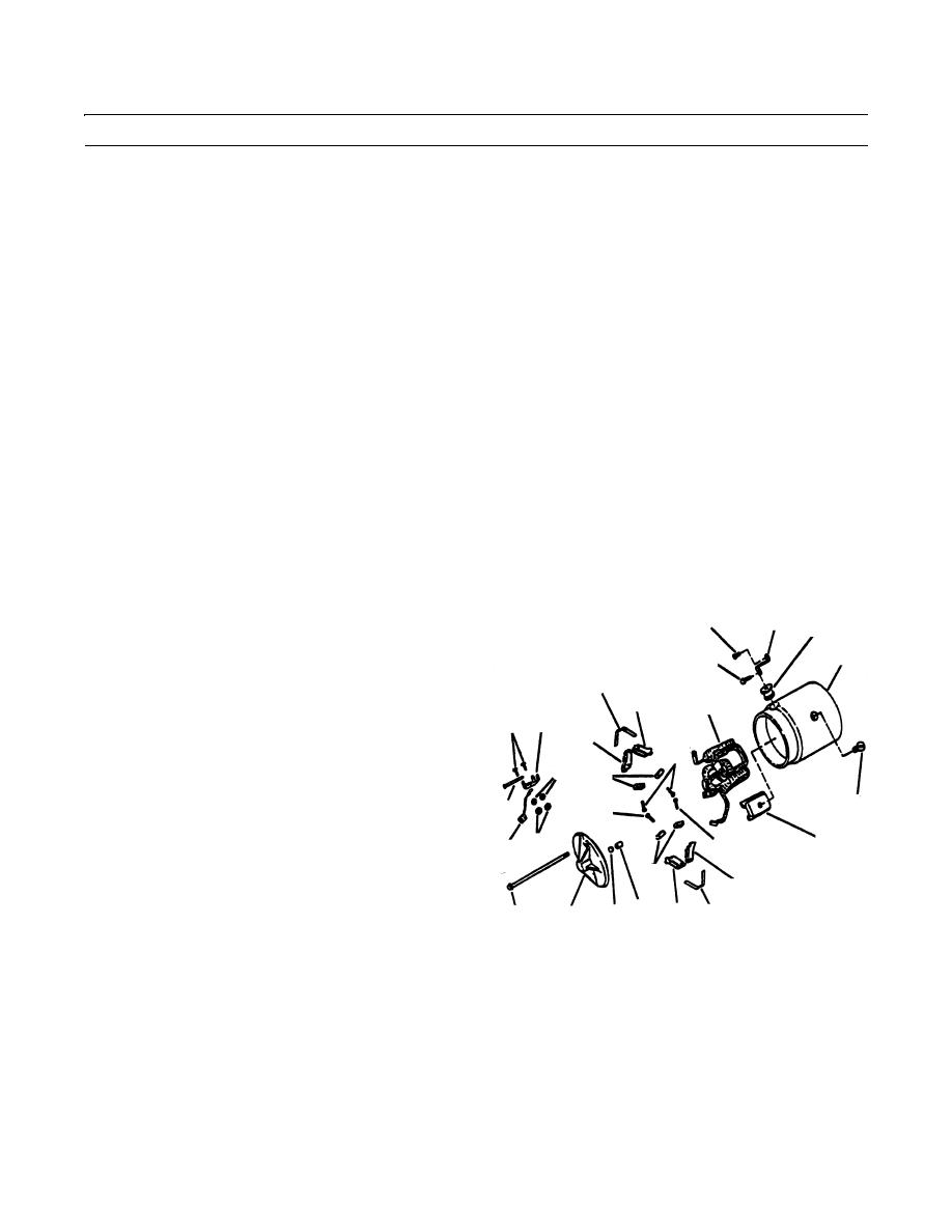
STARTER ASSEMBLY MAINTENANCE (152 HP) - CONTINUED
0286 00
ASSEMBLY - CONTINUED
NOTE
Clamp drive housing in a padded vise.
10.
Position center bearing retainer (41) to drive housing (10).
11.
Place shift lever (39) in drive housing (10) and secure with screw (36), nut (37) and new lockwasher (38).
12.
Install plunger (35) and pin (34).
13.
Install plunger return spring (33) and new gasket (32).
14.
Install solenoid switch (28), two screws (30) and two new lockwashers (31).
15.
Position contact (29) between cover (26) and solenoid switch housing (28). Align new gasket (27) and secure cover (26)
to solenoid switch housing (28) with two capscrews (25).
NOTE
If pole shoes have one long lip, install pole shoes so long lip points in direction of armature rotation. Also,
observe match marks made before removal.
If supports were removed, use service parts to secure supports during step 17, below.
16.
If removed, install field coil (22) and pole shoes (23). Secure pole shoes (23) with eight screws (24). Use care to prevent
grounding or shorting coils as pole shoes are secured.
17.
If removed, secure two supports (16), and two brush ground leads (20) with four studs (53), four lockwashers (54) and
four nuts (55).
18.
Install two springs (15), two grounded brush holders
1
2
11
(13), two insulated brush holders (14) and two pins
(12).
8
7
19.
Install two brushes (19) in grounded brush holders
15
(14). Secure brushes (19) and brush ground leads (20)
13
22
using two screws (17).
16
53
14
20.
Install two brushes (19) in insulated brush holders (13)
17
and secure with two screws (18).
54
19
21.
Install new grommet (11) and connector (2).
24
22.
Place brake washer (42) on armature (9).
18
12
23.
Carefully lower field frame (8) onto armature (9),
23
55
18
20
making certain that brushes (19) clear commutator
bars and no interference occurs between pole shoes
19
(23) and armature (9). Install screw (7) to secure con-
14
nector (2) to field coil (22) terminal.
5
13
15
3
4
6
409-1115
24.
If removed, press new bearing (5) into bore in coil end
frame (4). Soak wick (6) in lubricating oil, and install.
25.
Check to be sure that brushes (19) are making proper contact with commutator, and that all internal electrical connec-
tions have been correctly made. Then, install coil end frame (4) and through bolts (3). Secure connector (2) to solenoid
switch (28) terminal using screw (1).
26.
Install starter (WP 0064 00).
27.
Start engine and check for proper operation (TM 10-3930-660-10).
END OF WORK PACKAGE
0286 00-5/(-6 Blank)
|
|
Privacy Statement - Press Release - Copyright Information. - Contact Us |
