 |
|||
|
|
|||
|
|
|||
| ||||||||||
|
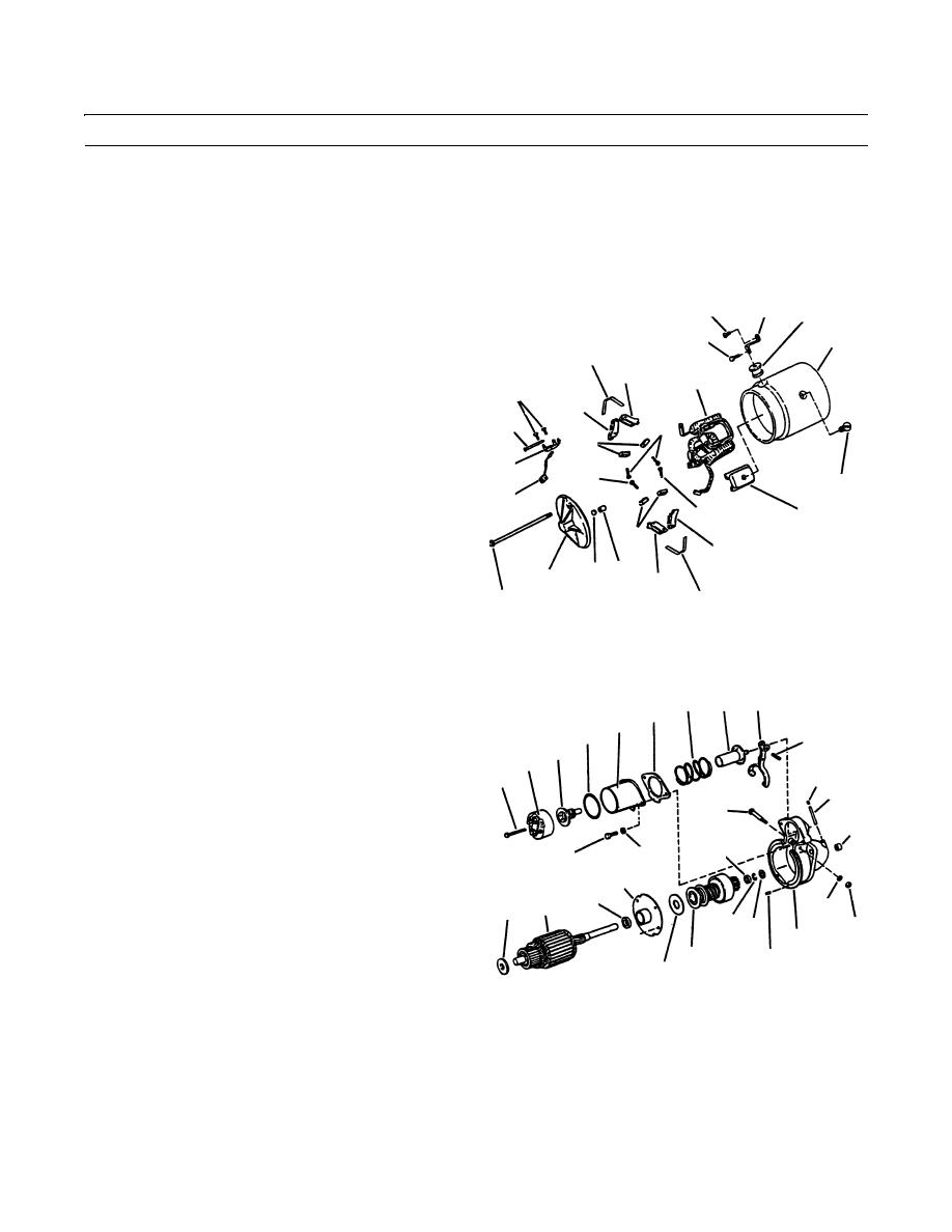
|
 TM 10-3930-660-24-2
STARTER ASSEMBLY MAINTENANCE (152 HP) - CONTINUED
0286 00
DISASSEMBLY - CONTINUED
NOTE
Remove field winding coil only if known to be grounded or open. If it is being removed, use a pole spreader
and a pole shoe screwdriver.
10.
Match-mark all four shoes (23) and adjacent area of
1
2
11
field frame (8), to ensure proper installation.
7
8
11.
Remove eight screws (24), four shoes (23) and field
15
winding coil (22).
13
22
21
14
12
17
19
16
18
24
20
18
23
19
14
5
6
4
13
3
15
409-1107
12.
Remove two capscrews (25) and separate cover (26)
35 39
33
32
and gasket (27) from solenoid switch housing (28).
28
Remove contact (29). Discard gasket.
27
34
29
13.
Remove two screws (30) and lockwashers (31). Dis-
26
card lockwashers.
25
51
52
14.
Remove solenoid switch (28), gasket (32) and plunger
36
return spring (33). Discard gasket.
50
15.
Remove pin (34) and plunger (35).
46
30
31
16.
Remove screw (36), nut (37), lockwasher (38) and
41
shift lever (39). Discard lockwasher.
48
9
42
38
17.
Remove brake washer (42) and armature (9), with
47 45
washer (43), motor drive (44) and thrust washer (45).
37
10
18.
Using a short pipe nipple, or other suitable metal cyl-
44
49
inder, and a hammer, drive pinion stop (46) toward
43
motor drive (44) until retaining ring (47) is exposed.
409-1108
Remove retaining ring (47).
19.
Separate armature (9), center bearing plate (41),
washer (43), motor drive (44) and pinion stop (46).
20.
If required, remove center bearing (48) from center bearing retainer (41).
21.
Remove parts (49 thru 52) from drive housing (10), as required, for replacement. Discard lockwasher.
0286 00-2
|
|
Privacy Statement - Press Release - Copyright Information. - Contact Us |