 |
|||
|
|
|||
|
|
|||
| ||||||||||
|
|
 TM 10-3930-660-24-2
ALTERNATOR ASSEMBLY MAINTENANCE (165 HP) - CONTINUED
0285 00
ASSEMBLY - CONTINUED
25.
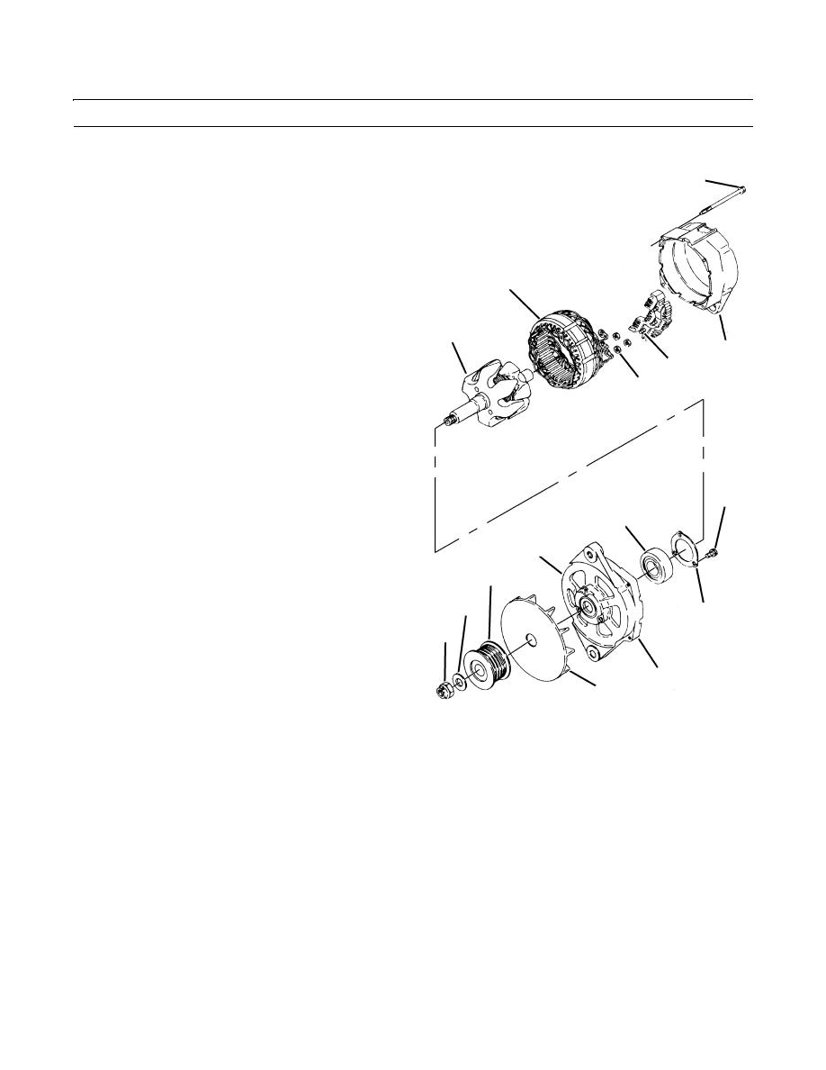
Position stator assembly (10) on rear frame (7) so that
8
three stator terminal clips (65) are fitted on three studs
(15).
26.
Gently press stator assembly (10) into rear frame (7)
so that it is properly seated.
27.
Install three nuts (14) on protruding studs.
10
28.
Install rotor assembly (9) on front frame (6).
29.
Pack roller bearing (13) with Delco-Remy lubricant
9
and position bearing in front frame (6).
7
30.
Install retainer plate (12) and three screws (11) in front
15
frame (6).
14
31.
Use press to install bearing (13) in front frame (6) on
rotor assembly (9).
32.
Install front frame (6) and rotor assembly (9) on rear
frame (7).
NOTE
11
Brushes must be retained before front and rear
13
frame sections can be assembled.
5
33.
Push brushes (49) into brush holder assembly (29) and
3
insert a stiff piece of wire through hole provided in
rear frame (7). Wire should then be inserted into
2
retaining hole in brush holder assembly (29).
12
1
NOTE
Ensure bracket frame holes are correctly aligned
6
when assembling frame halves. Two large
bracket holes in alternator frame should be
409-1858
aligned.
34.
Carefully position front frame (6) and rotor assembly (9) into rear frame (7).
35.
Install four screws (8) into alternator (5).
36.
Remove wire from rear frame (7).
37.
Install fan (4) and pulley (3) with washer (2) and locknut (1). Torque locknut to 75 lb-ft (102 Nm).
38.
Install alternator (WP 0063 00).
39.
Run engine and check for proper operation (TM 10-3930-660-10).
END OF WORK PACKAGE
0285 00-8
|
|
Privacy Statement - Press Release - Copyright Information. - Contact Us |