 |
|||
|
|
|||
|
|
|||
| ||||||||||
|
|
 TM 10-3930-660-24-2
ALTERNATOR ASSEMBLY MAINTENANCE (165 HP) - CONTINUED
0285 00
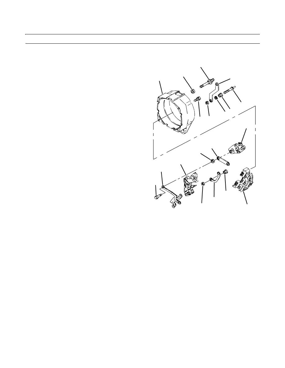
ASSEMBLY - CONTINUED
10.
Install relay terminal (33) and diode trio (27) on rear
17
frame (7).
19
11.
Position relay terminal (33) in rear frame (7).
23
7
12.
Position insulator (32) and relay terminal connector
(31) on relay terminal (33).
13.
Start nut (30) on relay terminal (33).
14.
Position opposite side of relay terminal connector on
26
brush holder assembly (29).
24 25
15.
Position diode trio (27) on rectifier bridge assembly
33 22
(21).
20
16.
Install insulated screw (28) on brush holder assembly
(29).
17.
Tighten nut (30).
16
18.
Position indicator light terminal (26) on rear frame (7).
18
19.
Position insulator (25) on indicator light terminal (26).
29
20.
Position stud connector (23) and washer (24) on recti-
fier bridge assembly (21) and indicator light terminal
27
(26).
28
32
31
30
21
TR01427
409-1859
21.
Install nut (22) on indicator light terminal (26).
22.
Install output terminal (17) and stud connector (16) on rear frame (7).
23.
Position stud connector (16) on output terminal (17) and regulator (20).
24.
Install nut (18) and nut (19).
0285 00-7
|
|
Privacy Statement - Press Release - Copyright Information. - Contact Us |