 |
|||
|
|
|||
|
|
|||
| ||||||||||
|
|
 TM 10-3930-660-24-2
TURBOCHARGER ASSEMBLY REPAIR (152 HP) - CONTINUED
0281 00
ASSEMBLY - CONTINUED
CAUTION
Do not allow impeller to turn when installing locknut. Failure to prevent impeller from turning will result in
improper balance and premature component failure.
NOTE
Locknut has left-hand treads, be sure to turn locknut counterclockwise when installing.
21.
Install new locknut (9) onto shaft. Torque locknut to 120 lb-in (163 Nm).
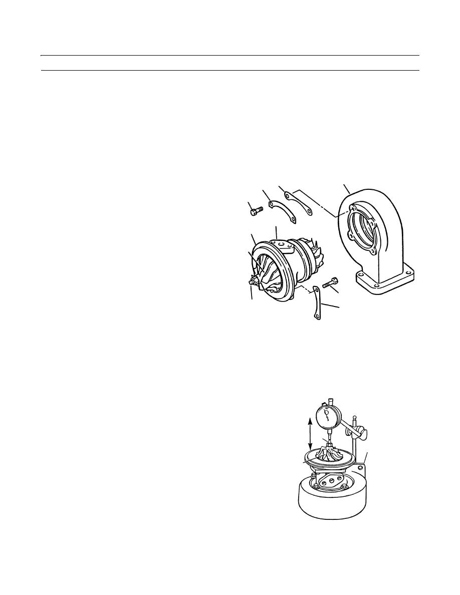
22.
Install bearing housing (2), impeller (10) and shaft
3
23
22
(24) into turbine housing (3) as an assembly.
21
23.
Align match marks on bearing housing (2) and turbine
housing (3) that were made at disassembly.
24.
Apply Loctite 767-64 to new capscrew (21) threads.
2
13
25.
Install two new lock plates (22), one clamping plate
(23), and four new capscrews (21) into turbine hous-
10
ing.
26.
Torque capscrews (21) to 100 lb-in. (136 Nm).
27.
Bend lock plate (22) tabs up to secure capscrews (21).
11
24
12
409-1081
28.
Install two new lock plates (12) and four capscrews (11) through bearing housing (2) and into diffuser (13).
29.
Torque capscrews (11) to 50 lb-in. (68 Nm).
CAUTION
Ensure scribe marks on diffuser, bearing housing and turbine housing are properly aligned during assembly.
Failure to properly align components could result in premature component failure.
30.
Bend lock plate (12) tabs up to secure capscrews (11).
31.
Attach a dial indicator to the turbine housing (3).
Adjust dial indicator so that plunger is against shaft
(24) end.
24
32.
Set dial indicator to zero.
3
33.
Move shaft (24) and impeller (10) assembly back and
10
forth and read end play on dial indicator. If end play is
less than 0.001 in. (.0254 mm), or greater than 0.003
in. (.0762 mm), disassemble turbocharger and check
for problem. Replace defective parts and assemble.
34.
To measure radial clearance of shaft (24), attach a dial
indicator to turbine housing. Adjust dial indicator
409-1082
plunger so that plunger is against end of impeller (13)
between fins and jamnut (9).
0281 00-6
|
|
Privacy Statement - Press Release - Copyright Information. - Contact Us |
