 |
|||
|
|
|||
|
|
|||
| ||||||||||
|
|
 TM 10-3930-660-24-1
MLRS ATTACHMENT CONTROL VALVE ASSEMBLY REPLACEMENT - CONTINUED
0176 00
REMOVAL - CONTINUED
15,16,17,18
7.
Tag eight electrical connectors (11).
11
8.
Loosen eight connector retaining screws (12).
11
NOTE
Gaskets (13) placed between connectors
and valve may drop out when connectors
12
12
are unplugged.
13
13
9.
Unplug eight electrical connectors (11) from valve.
NOTE
Secure valve during the following proce-
dure so it does not drop.
409-665
14,15,16
10.
Remove bottom capscrew (14), lockwasher (15) and
spacer (16). Discard lockwasher.
11.
Remove top two hex nuts (17), lockwashers (15), spacers (16) and capscrews (18). Discard lockwashers.
12.
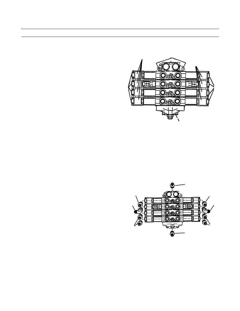
Remove three adapters (19) from valve.
13.
Remove two elbows (20) from valve.
14.
Remove four adapters (21) from valve.
15.
Remove adapter (22) from valve.
INSTALLATION
1.
Install adapter (22) to valve.
19
2.
Install four adapters (21) to valve.
19
19
3.
Install two elbows (20) to valve.
20
20
4.
Install three adapters (19) to valve.
5.
Position and support valve on vehicle.
6.
Apply loctite to two capscrews (18). Install two spac-
21
ers (16), two capscrews (18), two new lockwashers
21
(15) and two nuts (17).
22
409-666
7.
Apply loctite to capscrew (14). Install spacer (16),
new lockwasher (15) and capscrew (14).
NOTE
Install gasket (13) on each electrical connector before installing connector to valve.
8.
Connect eight electrical connectors (11) as tagged and tighten eight connector retaining screws (12), to secure electrical
connectors.
9.
Connect eleven hydraulic hoses (9) to valve fittings (10) as tagged.
0176 00-3
|
|
Privacy Statement - Press Release - Copyright Information. - Contact Us |