 |
|||
|
|
|||
|
|
|||
| ||||||||||
|
|
 TM 10-3930-660-24-1
CIRCUIT BREAKERS REPLACEMENT - CONTINUED
0071 00
REMOVAL - CONTINUED
NOTE
Tag all wire leads and circuit breaker terminals
8
7
5
for use during installation.
4
2.
Remove two nuts (4) and two lockwashers (5) from
9
circuit breaker (6). Remove wire lead (7) from circuit
breaker. Discard lockwashers.
3.
Remove circuit breaker (6) by pulling circuit breaker
straight out of bracket (8).
4.
If necessary, remove bracket (8) from cab (9).
5.
Remove two nuts (10) and two lockwashers (11)
securing each end of bracket (8). Remove bracket.
Discard lockwashers.
6.
From outside of cab (9) remove two screws (12).
6
12
10,11
409-4000
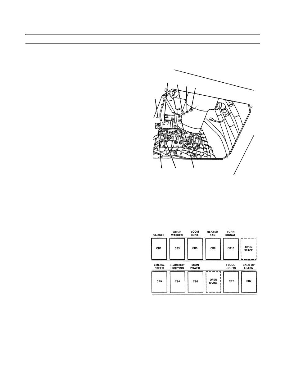
INSTALLATION
NOTE
The circuit breakers are arranged as shown in the figure below.
Circuit
Breakers
AMPS
CB1
6
CB2
6
CB3
6
CB4
15
CB5
6
CB6
40
409-280
CB7
10
CB8
10
CB9
6
CB10
10
0071 00-2
|
|
Privacy Statement - Press Release - Copyright Information. - Contact Us |
