 |
|||
|
|
|||
|
|
|||
| ||||||||||
|
|
 Legend for Figure 5-160
Ring Segment
17.
Plate
25.
Bushing
Tilt Cyl. Assy.
9.
1.
Boot
18.
Lockwasher
26.
Packing Set
10.
Barrel
2.
Retainer
19.
Capscrew
27.
Shim
11.
u-cup
3.
Bushing
20.
Lub-Fitting
28.
Retainer
12.
W e a r Ring
4.
Adaptor
21.
Gland
29.
Lockwasher
13.
Spacer
5.
22.
Spacer
30.
Retainer
14.
Capscrew
O-Ring
6.
Spring
23.
Retainer
31.
15.
Wiper
Back-up Ring
7.
Packing Kit.
24.
Capscrew
32.
Pin
16.
Gland Assy.
8.
b. Remove tilt cylinder pivot pins at rear
b. Install a new back-up ring and O-ring on
mounting and at upright. Remove tilt cylinder
the check valve plug with the O-ring toward
from machine.
the spring and bail. Place the bail and spring
c . An exploded view of the tilt cylinder is
in the body and install the plug. Be sure the
shown on the preceding page to aid in dis-
hole in the plug lines up with the stud hole
assembly and reassembly of the unit. See figure
in the body.
5-160.
C. Install lower spool seal and back-up ring
on valve spool, making sure that scarfed ends
of back-up ring are closed up and correctly
seated.
d. Install one "C" washer at each end of the
centering spring. The fiat side of the "C"
washer faces away from the spring when installed.
e . Install the upper spool quad ring on the
s p o o l , and install the O-ring on the spring
cover sleeve face.
f . Carefully position spring cover and sleeve
over the spool and against valve body. Install
spring cover screws and tighten to IO foot/
pounds torque.
g. After installation of valve and connection
to operating lever linkage, check valve opera-
t i o n . Spools should return to neutral auto-
matically when the control lever is released.
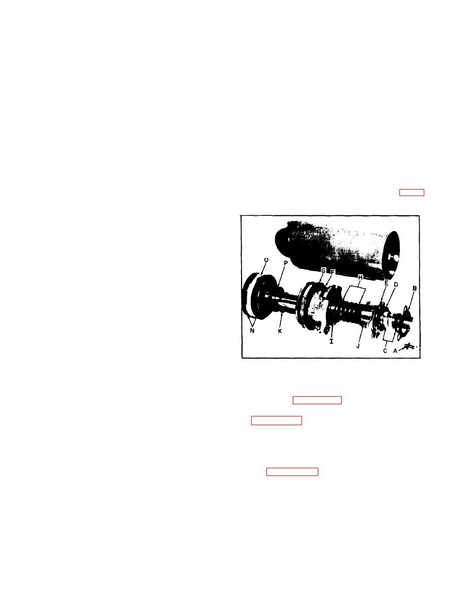
Figure 5-161.
Tilt Cylinder Components.
The centering spring force is approximately 40
pounds. If more force is necessary, check
5-135 DISASSEMBLY.
linkage for binds.
a. Refer to figure 5-160 for detailed parts
5-133 TILT CYLINDERS.
identification and proceed as outlined below:
5-134 REMOVAL. Should it be found that the
b. Figure 5-161 shows components of the tilt
tilt cylinders will not hold upright at desired
cylinder and body. Refer to this figure and
a n g l e o f t i l t , it will be necessary to remove
remove three retainer bolts (A) securing the
and disassemble cylinder to determine the
cover (6). seal guard kit (C), retainer (D) and
faulty condition.
shims (E). Pull these components from end of
cylinder and piston rod.
a . Tilt upright to full forward position,
disconnect hose lines at front and rear of
c. See figure 5-162 for gland details and
cylinder.
loosen gland bolts (F), using suitable wrench.
Then, using a screwdriver, rotate each bolt
x
xxxxxxxxxxxxxxxxxxxxxxx
until head is against gland assembly.
X
X
X
WARNING
X
d. Now tap gland assembly inward into cylinder,
X
X
being careful not to mar, nick, scratch, etc.,
X
X
SECURE UPRIGHT WITH A CHAIN TO PREVENT
X
the piston rod. Use a wooden or plastic mallet
X
X
that does not have a metal frame that might
X
FALLING.
contact piston rod when tapping gland.
X
X
x
xxxxxxxxxxxxxxxxxxxxxxx
5-96
|
|
Privacy Statement - Press Release - Copyright Information. - Contact Us |