 |
|||
|
|
|||
|
Page Title:
SPECIFICATIONS FOR TILT LOCK VALVE |
|
||
| ||||||||||
|
|
 5-128
REASSEMBLY:
CAUTION
USE GREAT CARE DURING ASSEMBLY NOT T O
STEP 1.
Install spool check ball, Spring, plug
and internal snap ring. It may be
SCRATCH OR DAMAGE SURFACES INS IDE VALVE.
necessary to press or drive plug into
position SO the snap ring seats in
recess.
Install new O-rings and reinstall plugs
STEP 3.
in valve body, I f tilt lock valve is
not to be installed on truck
STEP 2.
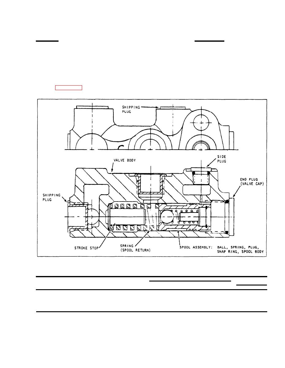
Install stroke stop, spool return spring
immediately, insert shipping plugs in
and spool assembly (preassembled in
all uncovered openings in valve body to
Step 1) into valve body (as shown in
prevent dirt or particles from entering
valve.
install valve cap, tightening properly.
Fig. 13343
SPECIFICATIONS FOR TILT LOCK VALVE:
STROKE STOP
SPOOL RETURN SPRING SPECIFICATIONS
BODY
SPOOL ASSEMBLY
DIMENSIONS
FREE
MAX.
MIN.
TYPE
(DISCARD & REPLACE
COMPRESSED
CLARK PART NUMBER
LGTH ROD 0.D.
H E I G H T I.D.
O.D.
HEIGHT
AS COMPLETE UNIT)
.438
Note 2
1.029
1.540.029" Note 1
.968" @
yes
CASTING
233471
(MIN) (MAX)
100-120 lbs
NOTES:
1 Spring must work over .438 inch rod (test with the stroke stop),
2 Spring must move freely inside hole .750 inch minimum.
5-94A
|
|
Privacy Statement - Press Release - Copyright Information. - Contact Us |