 |
|||
|
|
|||
|
|
|||
| ||||||||||
|
|
 b. Then reverse the lead connections to the
grounded heat sink and same terminal (or
If both readings are the same,
connector).
r e p l a c e the rectifier bridge. A good rec-
tifier bridge will give one high and one
low reading. Repeat this same test be-
tween the grounded heat sink and the other
two terminals, and between the insulated
heat sink and each of the three terminals.
This makes a total of six checks, with two
readings taken for each check.
c. The ohmmeter check of the rectifier bridge,
and of the diode trio as previously covered,
is a valid and accurate check. DO NOT re-
place either unit unless at least one pair
of readings is the same.
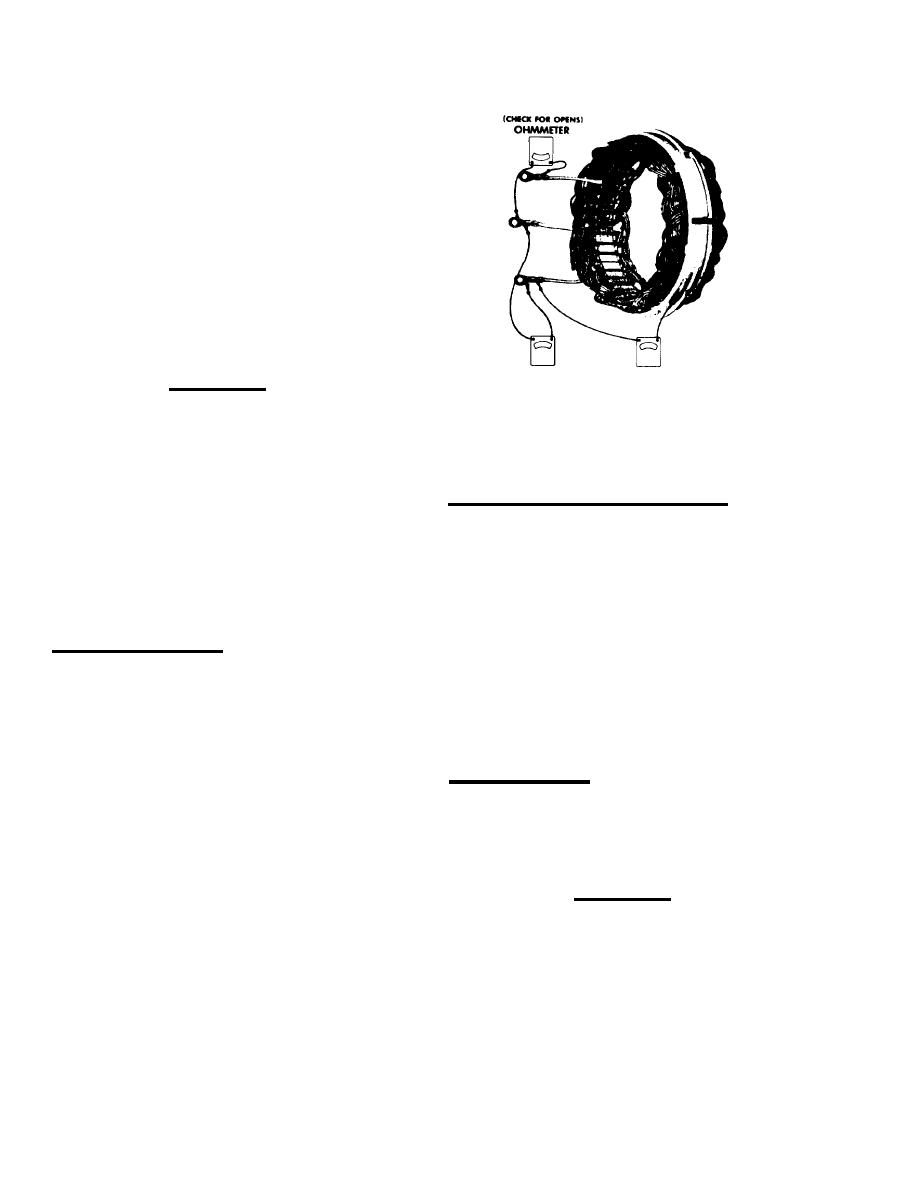
OHMMETER
OHMMETER
CAUTION
(CHECK FOR OPENS)
(CHECK FOR GROUNDS)
Plate 12342. Checking Stator Windings
DO NOT USE HIGH VOLTAGE TO CHECK THESE
shorted stator can cause the indicator
UNITS, SUCH AS A 110-VOLT TEST LAMP.
lamp to be on with the engine at low
speed.
d. To replace the rectifier bridge, remove
the attaching screws, and disconnect the
BRUSH HOLDER AND REGULATOR REPLACEMENT:
capacitor lead.
After removing the three attaching nuts,
NOTE
the stator and diode trio screw (plates 12340
and 12341). the brush holder and regulator may
There is an insulator between the insu-
be replaced by removing the two remaining screws.
lated heat sink and end frame (plate
12340). Rectifier bridges may vary in
Notice the two insulators located over the
appearance but are completely inter-
top of the brush clips in plate 12338, and that
changeable in these generators.
these two screws have special insulating sleeves
above the threads. The third mounting screw may
CHECKING STATOR WINDINGS:
If not,
or may not have an insulating sleeve.
this screw must not be interchanged with either
a. The stator windings may be checked with
one of the other two screws, as a ground may
a 110-volt test lamp or an ohmmeter.
result, causing no output or uncontrolled gener-
ator output. Requlators may vary in appearance
b. If the lamp lights, or if the meter rea-
but are completely interchangeable in these
ding is low when connected from any stator
lead to the frame, the windings are groun-
ded.
SLIP RING SERVICING:
c . If the lamp fails to light, or if the
I f the slip rings are dirty, they may be
meter reading is high when successively
cleaned and finished with 400-grain or finer
connected between each pair of stator
p o l i s h i n g cloth. Spin the rotor and hold the
leads on 10-S1 Series, the windings are
polishing cloth against the slip rings until
open (plate 12342).
they are clean.
CAUTION
THE ROTOR MUST BE ROTATED IN ORDER TO
CLEAN THE SLIP RINGS EVENLY; CLEANING
d. A short circuit in the stator windings
i s difficult to locate without laboratory
SLIP RINGS BY HAND WITHOUT SPINNING
test equipment due to the low resistance
of the windings. However, i f all other
ROTOR MAY RESULT IN FLAT SPOTS ON
electrical checks are normal and the gen-
erator fails to supply rated output, shor-
SLIP RINGS, CAUSING BRUSH NOISE.
Also, a
ted windings are indicated.
5-50F
|
|
Privacy Statement - Press Release - Copyright Information. - Contact Us |