 |
|||
|
|
|||
|
Page Title:
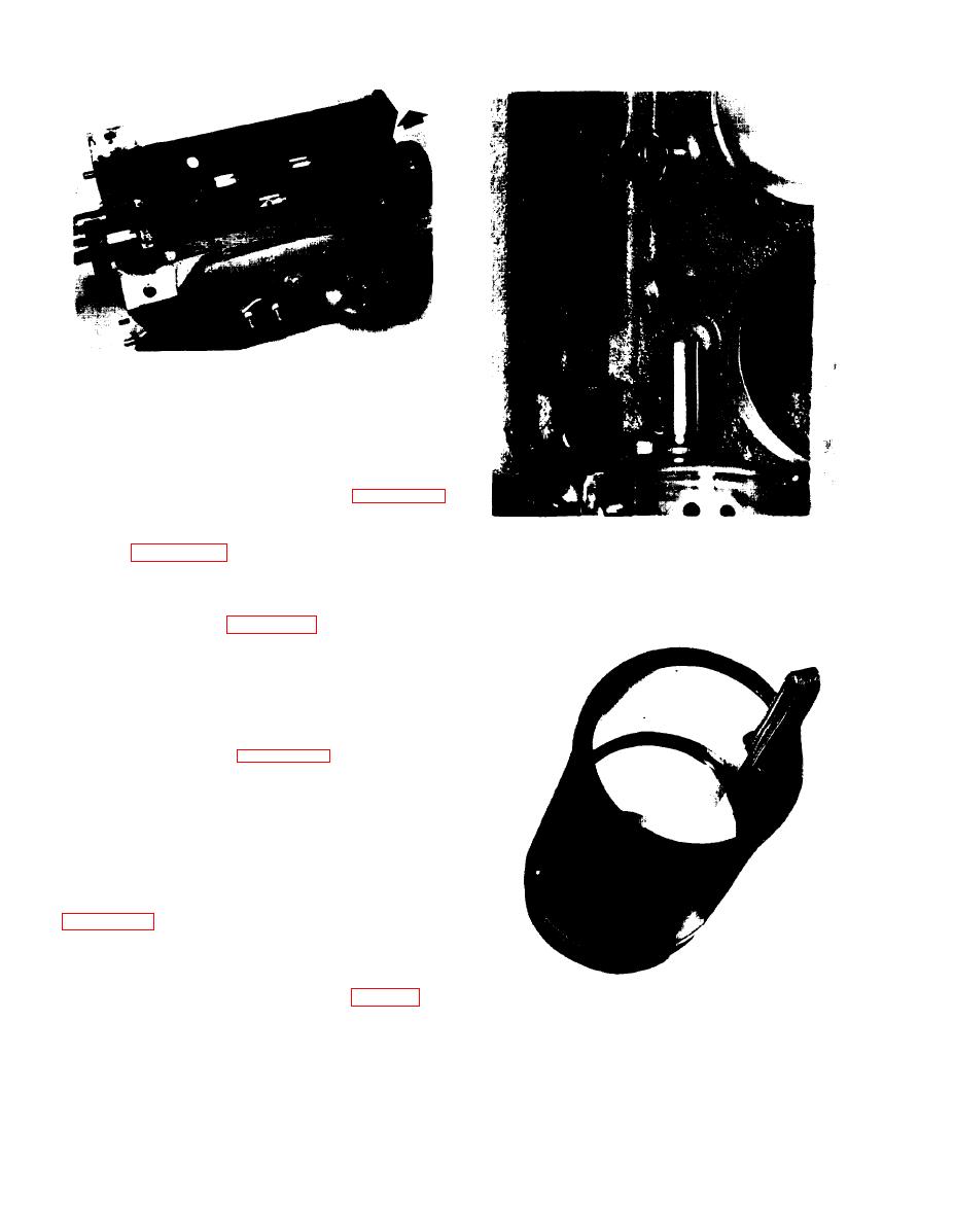
Figure 5-55. Crankshaft Removal |
|
||
| ||||||||||
|
|
 Figure 5-55. Crankshaft Removal
s. The cylinder sleeve may be removed by placing
d wooden block between the crankshaft and the
bottom of the cylinder sleeve and turning the
crankshaft, forcing the sleeve out. See figure 5-52.
After the cylinder sleeve has been lifted from its
seat, pull the sleeve up and out of engine block, as
Figure 5-56. Removing Valve Lifters
shown in figure 5-53.
t. Remove the main bearing caps one at a time,
and match mark each cap for proper position at
time of assembly. See figure 5-54.
u. Inspect bearings as they are removed for
abnormal conditions shown in figure 5-50.
v . Remove crankshaft by lifting upward out of
c r a n k c a s e , exercising care to prevent damage to
machined surfaces. See figure 5-55.
w. Carefully inspect crankshaft for wear, out of
round and rough areas on bearing surfaces.
x. Clean all oil passages and make sure they are
free of obstructions and foreign material.
y. Remove valve lifters one at a time, as shown in
they may be reinstalled in the same position.
z. Inspect lifters for excessive wear and replace as
n e c e s s a r y . Refer to specifications of Table 5 to
Figure 5-57. Measuring Ring Gap
determine wear limits.
5-36
|
|
Privacy Statement - Press Release - Copyright Information. - Contact Us |