 |
|||
|
|
|||
|
|
|||
| ||||||||||
|
|
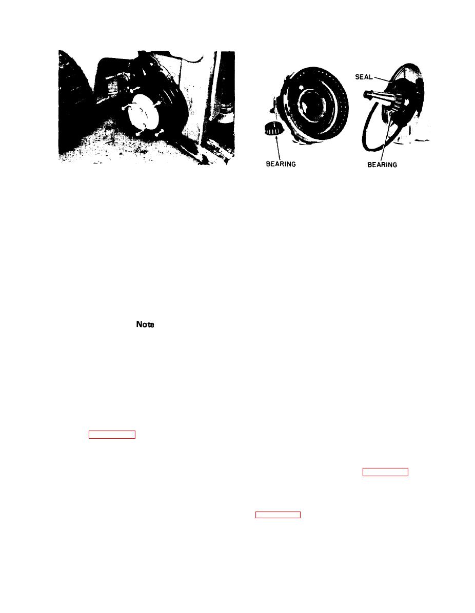
 Figure 477. Wheel Removed
Figure 478. Axle End Removed
soap thickner containing anti-wear, anti-rust and
4-75. CLEAN AND REPACK AXLE ENDS.
anti-oxidants with EP additives. To meet or exceed
Clark Specifications MS-107 and Timken Test 40
a. Every 1000 operating hours or every six
lbs. minimum (NLGI No. 1 or NLGI No. 2).
months of operation, whichever occurs first, clean
and repack the axle ends using a smooth stringy
4-74. ADJUSTMENT CHECK.
multi-purpose grease or refined mineral oil blended
with a lithium soap thickner containing anti-wear,
a. Inspect adjustment
of bearings by gripping top
anti-rust and anti-oxidants with EP additives. To
and bottom of tire,
chuck tire in and out to
meet or exceed Clark Specifications MS-107
determine looseness or
wobble. Now grip front and
additives.
rear side of tire, chuck
tire in and out to determine
looseness or wobble.
Test 40 lb. minimum (NLGI No. 1 or NLGI No. 2)
Shell Aluania EP Grease No. 1 or No. 2
Sun Prestige 741 EP No. 1 or
742 EP No. 2
Before making wheel bearing adjustment,
Gulfcrown Grease EP No. 2
be sure play (looseness or wobble) is in the
Amolith Grease EP No. 2
wheel bearings and not in the king pins. (If
Citgo HEP No. 1 or No. 2
wheel bearings need adjustment, clean and
Texaco Multifak EP No. 1 or
repack bearings before making adjustments.
Marfak All Purpose No. 2
Refer
to lubrication instructions in
Molub-Alloy General Purpose
preceding paragraph.)
Grease No. 1 or No. 2
or the equivalent of the above listed lubricants.
b. If bearings are loose and require adjustment,
refer to figure 4-76 and remove hub cap and
b . Tilt upright back. Place solid heavy blocks
under each upright rail. Tilt upright forward until
s p i n d l e cotter pin. Tighten nut with a 12 inch
vertical to the floor. This should allow the drive
wrench and at the same time rotate the wheel in
wheels to clear the floor. Remove the wheels
one direction and then in the other until there is
from the hub assembly. See figure 4-77.
a slight bind to be sure all bearing surfaces are in
contact. Then back off the nut l/6 to l/4 turn,
allowing the wheel to rotate freely. Secure nut at
c. Remove hub cap, cotter pin, washer, spindle
t h i s position with a new cotter pin and replace
nut and pull hub assembly from vehicle (see
hub cap.
4-55
|
|
Privacy Statement - Press Release - Copyright Information. - Contact Us |