 |
|||
|
|
|||
|
|
|||
| ||||||||||
|
|
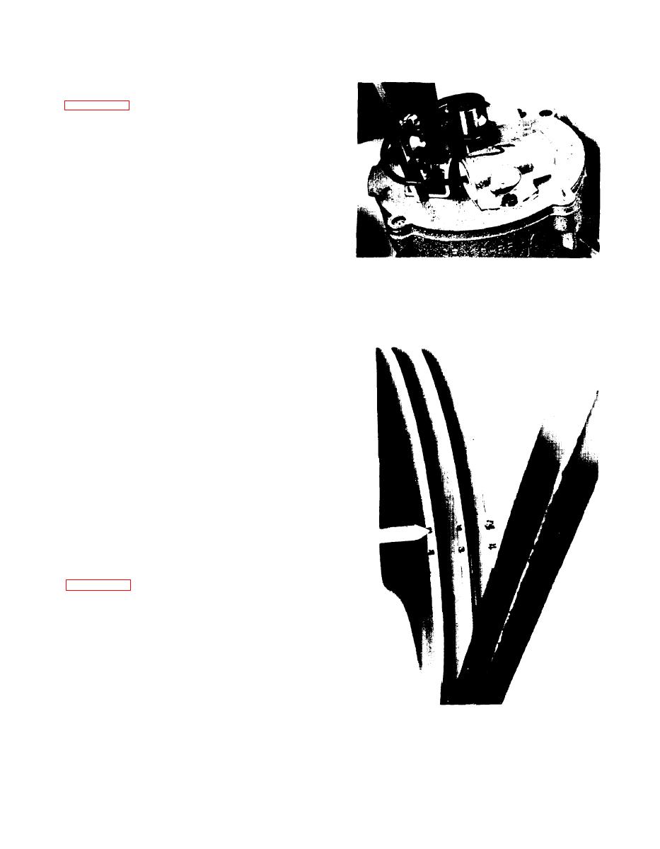 f. Insert a screwdriver blade into the adjustment
slot in point set and breaker plate as shown in
g . Rotate screwdriver blade until only a very
slight drag is felt on feeler gage. This represents
p r o p e r adjustment. Make certain that the screw
securing the stationary contact is tightened after
adjustment is made.
h . Set the ignition timing. If scope or a dwell
meter is used to adjust new points, be sure the
points are in proper alignment. Also, set the
contact dwell to the low setting.
4-49. POINT SET REPLACEMENT. If point set is
burned or badly pitted, it should be replaced as
Figure 4-49. Setting Point Gap
follows:
a. Remove the distributor cap and rotor.
b. Disconnect the primary and the condenser
wires from the breaker point assembly.
c. Remove the breaker point assembly and
condenser retaining screws. Lift the breaker point
assembly and condenser out of the distributor.
d. Place the new breaker point assembly and new
c o n d e n s e r in position and install the retaining
screws.
e. Align and adjust the breaker point assembly.
f. Connect the primary and condenser wires to
the breaker point assembly.
g. Install the rotor and the distributor cap.
4-50. IGNITION TIMING ADJUSTMENT. (See
figure 450.) Ignition timing is indicated by a
pointer affixed to the engine, which aligns with the
edge of the crankshaft pulley. The pulley is marked
with two notches, one indicating exact Top Dead
Center (TDC) at the time No. 1 spark plug fires.
The other notch indicates 5 before TDC. A neon
timing light is used to illuminate the pulley at the
time the spark plug fires.
a. Remove the plug wire from No. 1 spark plug.
Figure 4-50. Timing Pointer and Crankshaft Pulley
b. Install spark plug adapter on spark plug.
4-37
|
|
Privacy Statement - Press Release - Copyright Information. - Contact Us |
