 |
|||
|
|
|||
|
|
|||
| ||||||||||
|
|
 TM 10-3930-644-14&P
TOPIC 3. WHEEL CYLINDERS
2. Remove hydraulic line attached to wheel
A. DESCRIPTION
cylinder.
Remove wheel cylinder mounting
capscrews and remove cylinder.
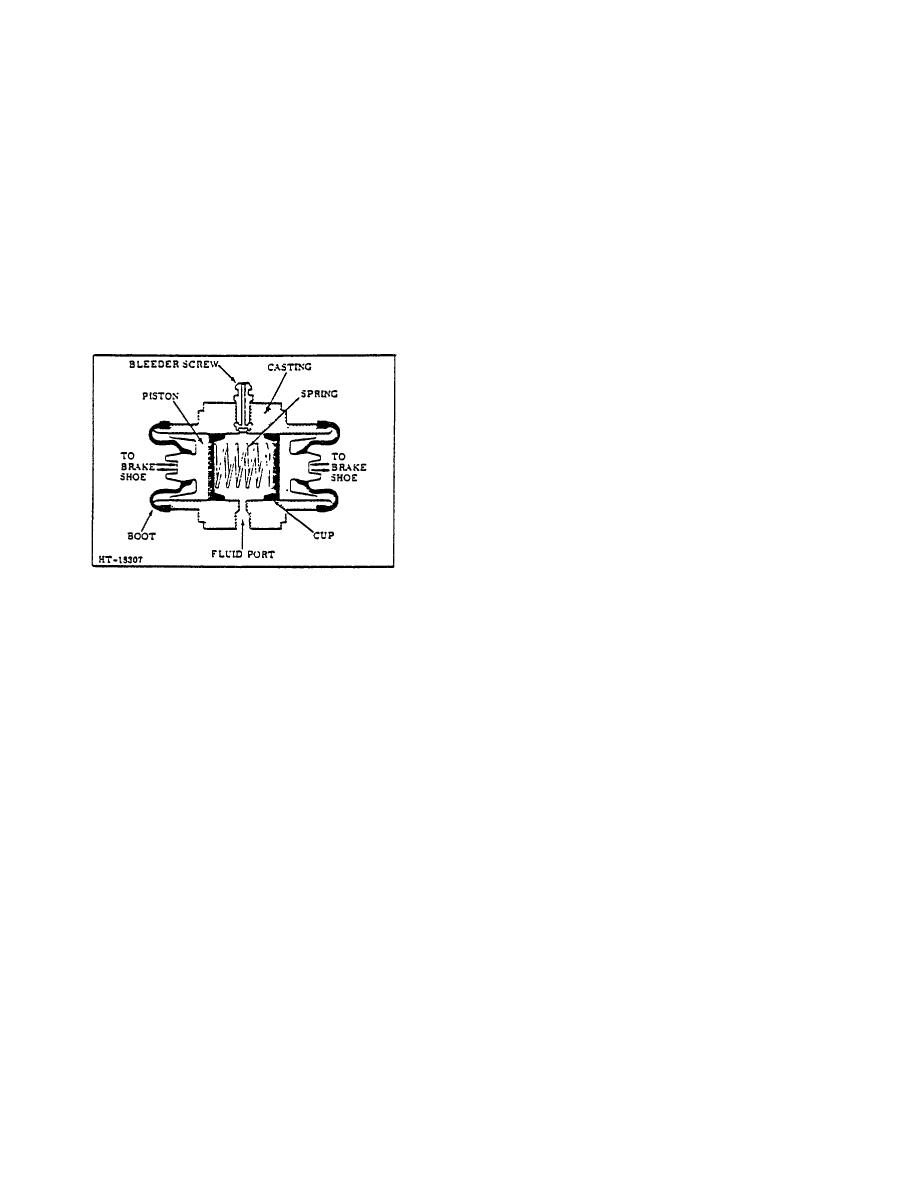
The hydraulic wheel cylinder houses two opposed
pistons which actuate the opposed brake shoes. (See
3. Pull boots from cylinder and push out internal
Figure 9.) The pistons, rubber cups, and springs are held
parts. Low pressure air at fluid inlet can be used
in place, in the cylinders, by the brake shoe mechanical
to remove cylinder components.
pressure.
The opened ends of the cylinders are
4. Clean all parts thoroughly and keep them clean
protected with rubber boots. Since the wheel cylinders
until unit is ready for assembly. Use lint-free
of a hydraulic brake system are a very important part of
cloth for cleaning.
the whole system, It is necessary that the following
reconditioning instructions are carefully followed:
CAUTION
Wash parts thoroughly in denatured
alcohol or clean brake fluid. Never
use gasoline, kerosene, pant thinner
or other mineral base solvents as
they will damage rubber components.
5. Thoroughly inspect all parts for wear, corrosion
or other conditions which might impair cylinder
action.
6. if wheel cylinder is to be honed, follow specific
instructions furnished with honing equipment, as
these instructions may vary.
NOTE
Cylinder honed oversize will leak and
must be discarded.
Figure 9. Wheel Cylinder
7. Lubricate all parts and cylinder walls with clean
brake fluid. laser each piston in its respective
B. SERVICE
end. Never try to push piston through length of
cylinder After cylinder is assembled, install
1. Remove wheel assembly, bearings and brake
cylinder boots.
Be sure they are properly
shoes.
(Refer to DRIVE UNIT REMOVAL,
located in grooves provided.
.MAINTENANCE MANUAL.)
8. Reassemble cylinder to backing plate.
Install
brake unit and wheel assembly.
TOPIC 4. PARKING BRAKE
A. DESCRIPTION
B. HAND BRAKE ADJUSTMENT
A dual shoe mechanical brake, mounted at the drive
To compensate for brake lining wear the hand brake
shaft, is used as a parking brake. The brake shoes are
lever must be adjusted. Refer to HAND BRAKE LEVER
actuated through a cable by an adjustable over-center
ADJUSTMENT La BRAKE SYSTEM MAINTENANCE
type lever mounted on the left hand cowl panel.
MANUAL.
The brake mechanism requires no lubrication except at
C. BRAKE SHOE ADJUSTMENT
time of reassembly. Brake actuating mechanism, such
as hand lever and linkage, should be lubricated
If the adjusting knob on the parking brake handle will no
periodically.
longer provide correct brake adjustment and sufficient
brake lining is still available, further adjustment is made
at the lower brake-cable yoke.
3-153
|
|
Privacy Statement - Press Release - Copyright Information. - Contact Us |
