 |
|||
|
|
|||
|
Page Title:
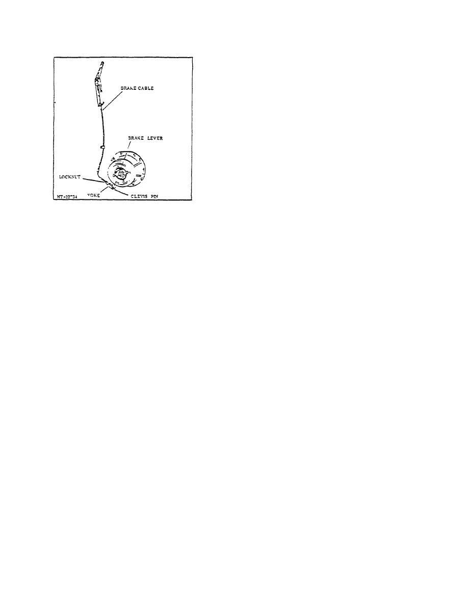
Figure 10. Adjustment at Brake Shoes |
|
||
| ||||||||||
|
|
 TM 10-3930-644-14&P
b. Remove toe and floor plates.
c. Remove cotter pin and clevis pin securing
brake cable to brake lever d. Remove
universal joint e.
Remove lockwire,
capscrews, and lockwashers and remove
brake drum from differential pinion flange.
f. Remove cotter pin and nut, then remove
hub from pinion shaft.
g. Remove brake lever and rollers from
backing plate h. Remove brake shoe
return springs and slide shoe and lining
assembly off backing plate.
i. Remove capscrews, lockwasher.
and
backing plate from differential carrier
housing assembly
2. Inspection
Figure 10. Adjustment at Brake Shoes
a. Check backing pate for distortion, loose or
sheared rivets, and worn pawls.
1. Remove adjusting knob lockscrew from parking
brake handle and back off knob four or five
turns. Brake must be in OFF position during
b. Check brake lining for wear or grease
saturation.
adjustment.
2. Remove floor plate.
c. Check brake shoes for worn pawl holes,
lever contact areas, or wear pads.
3. Remove clevis pin from yoke and loosen yoke
locknut.
d. Check brake drum for cracks, scoring, or
other damage. Replace damaged parts e.
Always replace shoe return springs during
4. Turn yoke la clockwise direction to shorten
length of cable Generally three or four turns will
reassembly
be sufficient.
3. Reassembly and Installation
5. Install yoke on brake lever and check
Reassembly and installation is the reverse of
adjustment by engaging hand brake handle. If
removal .and disassembly with the exception of
necessary, make further adjustment to yoke to
make certain brake shoes do not drag when
lightly coating the wear pans and pawls on the
backing plate, the lever, and the brake shoe
disengaged.
wear points with lubricant. Avoid excessive
6. After satisfactory, adjustments made, tighten
lubricant as grease soaked linings are
dangerous.
yoke locknut;: install cotter pin in yoke clevis
pin. Install locking screw in adjusting knob of
parking brake handle.
a. Replace backing plate, lockwashers
and
capscrews on differential carrier housing.
D. BRAKE SHOE REPLACEMENT
b. Slide shoe and lining assembly on backing plate
and replace brake shoe return springs.
When excessive adjustment is needed on parking brake
linkage, or when parking brake becomes ineffective in
holding truck securely, the brake shoes should be
c. Install brake rollers and brake lever on backing
plate.
checked and, if necessary, replaced. To check or
replace parking brake shoes the following procedure is
recommended:
d. Replace hub on pinion shaft and install nut and
cotter pin.
1. Removal and Disassembly
a. Place blocks ;a front and behind one of
the list truck wheels
3-154
|
|
Privacy Statement - Press Release - Copyright Information. - Contact Us |
