 |
|||
|
|
|||
|
|
|||
| ||||||||||
|
|
 TM 10-3930-644-14&P
cracking, external damage or damage from
2. Install a new seal in the pump body. When
pressing, or other defects which might impair
installing the seal make certain it is square with
efficient operation.
the seal bore and is firmly seated.
2. Check the bearing and shaft assembly by
3. Place the pump housing in an arbor press on a
rotating the bearing. If movement is rough or
suitable support and press the shaft and bearing
the bearing is binding or running dry from lack of
assembly into the bearing bore until the bearing
lubricant, the shaft and bearing assembly must
is firmly seated against the inside housing
be replaced.
shoulder.
CAUTION
NOTE
Do not wash the bearing assembly as
Care must be taken during this
it is permanently lubricated at the
operation to prevent damage to the
factory.
seal.
3. Inspect the face of the impeller hub, where it
4. Install the retainer rings in the front and rear of
contacts the seal, for any scoring or pitting. The
the bearing.
face must be smooth so as not to damage the
seal.
5. Using an arbor press, install the impeller on the
pump shaft until the impeller is flush with the end
4. Check the impeller seal for a smooth, flat
of the shaft. Revolve the impeller to make
surface. A light film of lubricant applied to the
certain that it is free to turn and firmly seated on
face of the seal facilitates seating and sealing.
the seal.
5. Always use a
new
pump
gasket
when
NOTE
reassembling.
If the impeller is properly seated on
the seal, a slight drag caused by the
mating faces of the seal assembly
and the impeller will be felt.
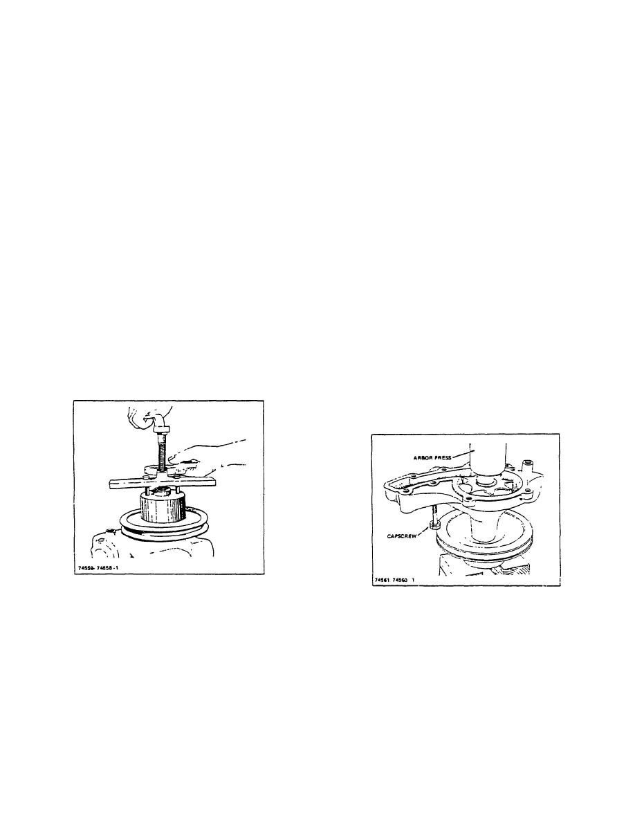
Figure 2-3. Removing Water Pump Pulley
Figure 2-4. Water Pump Assembly Showing Inserted
F. ASSEMBLY
Capscrew, Prior to Pulley Press Fit.
Reassemble the water pump by referring to Figure 2-1
G. INSTALLATION
for the relative location of the parts, and reversing the
sequence of the disassembly procedure as follows.
1. Measure pulley and shaft.
Recommended
minimum press fit is .001".
(Pulley must fit
1. When the bearing and shaft assembly is
snugly on shaft).
installed, use thick soap suds on the assembly
and the impeller seal to prevent damage to the
2. Insert capscrew in pump body BEFORE cross-
seal.
ing pulley on to shaft (Figure 2-4). Coat
R-155-1
3-107
|
|
Privacy Statement - Press Release - Copyright Information. - Contact Us |
