 |
|||
|
|
|||
|
|
|||
| ||||||||||
|
|
 TM 10-3930-644-14 & P
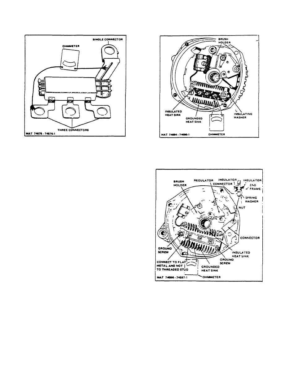
Figure 2-8. Diode Trio Check
Figure 2-9. Rectifier Bridge Check
4. Rectifier Bridge Check
Note that the rectifier bridge has a grounded
heat sink and an insulated heat sink connected
to the output terminal. Also, note the insulating
washer located between the insulated heat sink
and end frame.
To check the rectifier bridge, connect the
ohmmeter to the grounded heat sink and one of
the three terminals (Fig. 2-9). IMPORTANT: If
rectifier bridge is constructed as shown in Figure
2-10, connect ohmmeter pressing down very
firmly onto flat metal connector, and, not onto
threaded stud as in Figure 2-9. Then reverse
the lead connections to the grounded heat sink
and same terminal. If both readings are the
same, replace the rectifier bridge.
A good
rectifier bridge will give one high and one low
reading. Repeat this same test between the
grounded heat sink and the other two terminals,
and between the insulated heat sink and each of
the three terminals. This makes a total of six
checks, with two readings taken for each check.
The ohmmeter check of the rectifier bridge, and
of the diode trio as previously covered, is a valid
Figure 2-10. Rectifier Bridge Check
and accurate check. DO NOT replace either
unit unless at least one pair of readings is the
same.
R-146-1
3-87
|
|
Privacy Statement - Press Release - Copyright Information. - Contact Us |